Chair of Hydraulic Engineering

Research Laboratory - Measuring Equipment
The measuring equipment of the Hydraulic Engineering Research Laboratory consists of various devices operated in the hall – including the experimental flumes, the possibility for physical experiments as well as the thermotechnical test stand – and various measuring devices for field use.
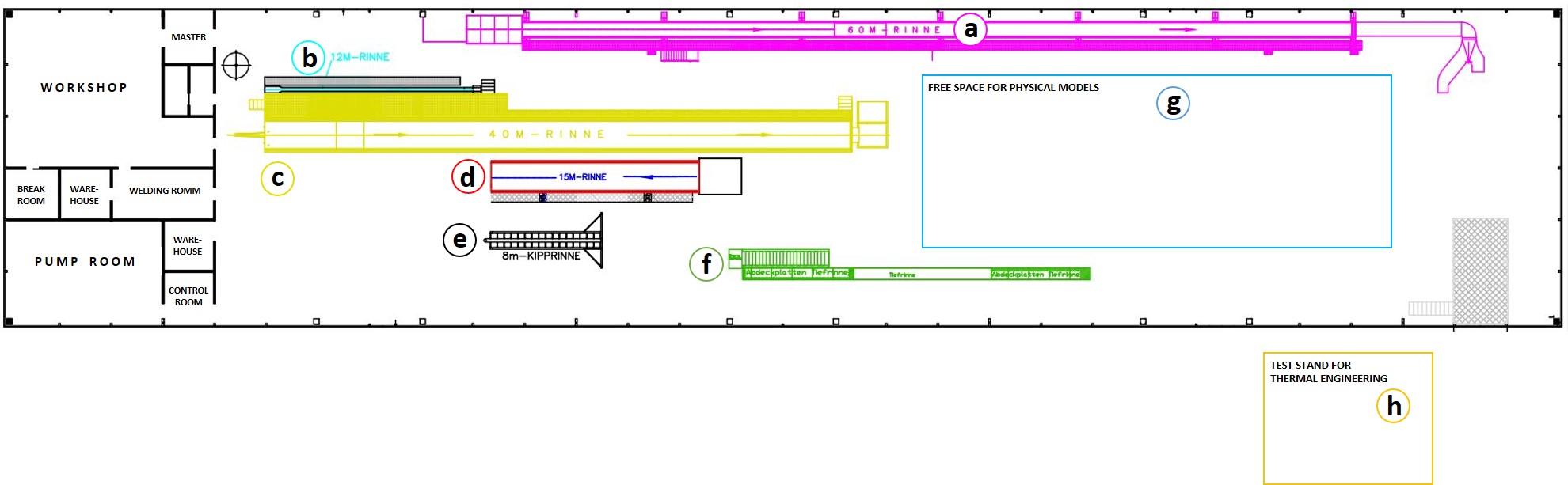


The Hydraulic Engineering Research Laboratory extends over a floor area of 113 m x 23 m. Thereby, the workshop rooms and technical infrastructure account for about 13 % of the area.
The measuring equipment of the research laboratory is
- six different flumes,
- a large open space for temporarily built physical models as well as
- a thermotechnical test stand.
In addition, various measuring instruments are available for measurements in the research laboratory as well as for field use.
The various facilities as well as the measuring instruments of the Hydraulic Engineering Research Laboratory are listed in more detail below.


Measuring instruments for laboratory and field use
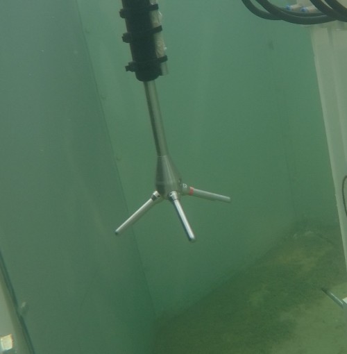
Acoustic Doppler Velocimeter (ADV)
Acoustic Doppler Velocimeters (ADV) belong to the Doppler measurement techniques and offer the possibility of non-contact measurement of flow velocities in a small measurement volume. The ADV also enables a high sampling rate. This measurement method provides three-dimensional point velocities in a local flow field.
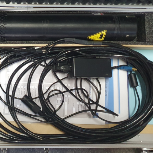
Acoustic Doppler Current Profiler (ADCP)
In the ADCP, the flow rate is determined on the basis of the measured velocities. The measuring principle of an ADCP is based on the frequency shift of reflected ultrasonic pulses (Doppler effect). The ADCP measurement provides simultaneous values at several measuring points of a perpendicular. Depending on the number of sound beams, one- to three-dimensional velocity fields are recorded.
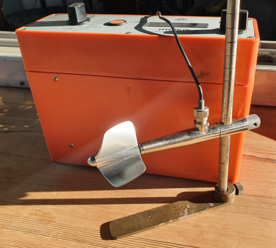
Mechanical Current Meter
For punctual velocity measurements, different mechanical current meters are available with different impeller's diameters and inclination. The rorations of the current meters are counted per time interval and displayed on the display unit via the so-called reed contact. The resulting value for the velocity is determined via so-called vane equations.
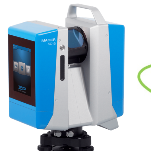
Terrestrial Laser Scanning (TLS)
Terrestrial laser scanning is a static, laser-based 3D method that repeatedly performs non-contact distance measurements. This enables the fast and easy recording of building contours, geometries, bottom positions. A sequential scanning method creates a high-resolution digital point cloud in the area of a 360° panorama around the TLS measuring device.
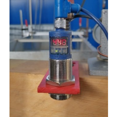
Ultrasonic Distance Sensor
Ultrasonic distance sensors are used for the metrological determination of water level positions and levels. In this time-of-flight measurement, a sensor emits a sound pulse. This pulse is reflected by the object to be detected (here: water surface). The time taken for the pulse to travel from the sensor to the object and back again is measured and converted into the corresponding distance.
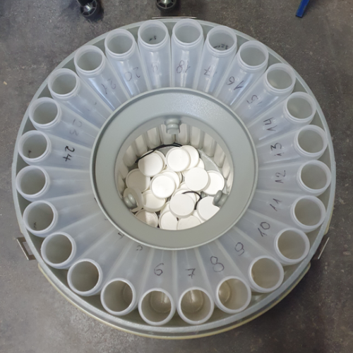
Water and Bottom Sampler
ISCO's portable and programmable sampler is enclosed in a protective plastic housing. The large handles make it safe and convenient to carry. Inside the sampler are 24 bottles for sampling and storage until the water samples are analyzed.
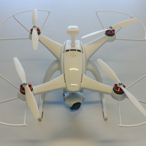
Drone
The drone is used in the field to fly over the survey areas. The quadrocopter available at the department provides with a photo resolution of 16 MP and video resolution of 4 K a good possibility to document the situation.
Contact
Sekretariat
wabau@wb.tu-...
work +49 6151 16-21165
Work
L5|01 310
Franziska-Braun-Straße 7
64287
Darmstadt