
How can the hydrothermal energy contained in flowing waters be used as efficiently as possible? The answer to this question and how the low temperature level of flowing waters can sustainably cover the space heating demand and the hot water supply of buildings is one of the task areas at the Department of Hydraulic Engineering.
In order to determine the influence of thermohydrodynamic parameters on heat extraction performance and to test different designs of heat source systems, the Department of Hydraulic Engineering operates a heat flow test rig under near-natural and reproducible field conditions in the outdoor area of the hydraulic engineering research laboratory. For this purpose, the heat flow test rig comprises a heat source circuit on the water side and a primary and heating circuit on the plant side.
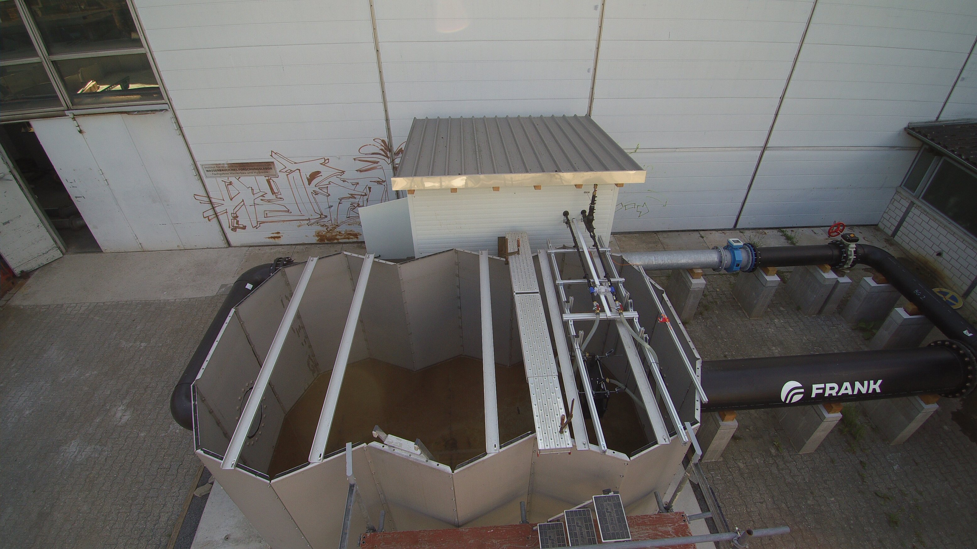
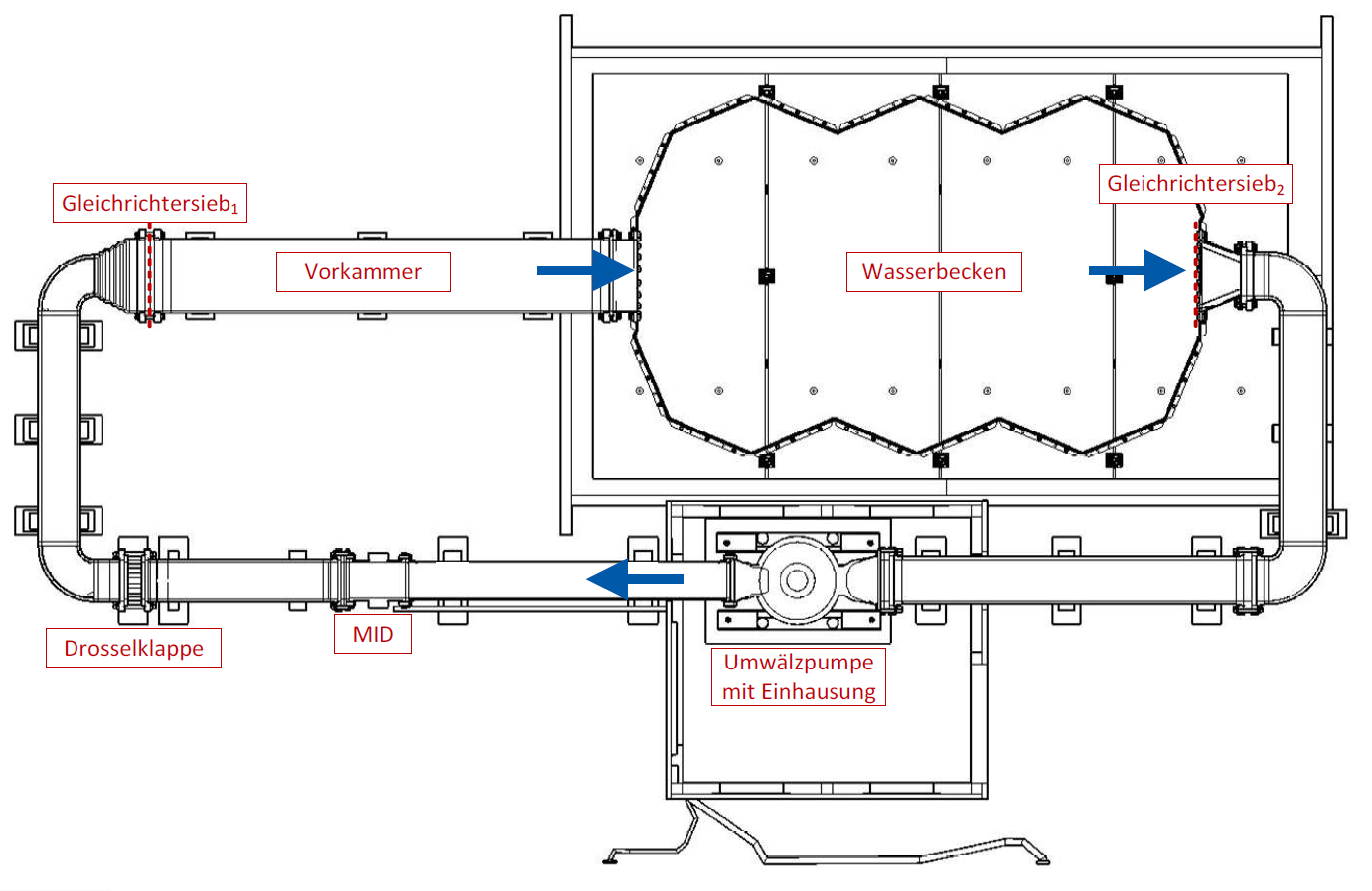
In the heat source circuit, a flow-through water basin represents the section of a flowing watercourse as an environmental heat source. For this purpose, a circulation pump directs the river water at the end of the basin via various pipes into a flow-calmed antechamber with a rectifier screen. Here, the large-scale eddies of the turbulent flow as well as the flow swirl can be reduced. Subsequently, the steady flow, which is as free of disturbances as possible, enters the water body of the water basin as a submerged jet and forms the usable examination area with an almost uniform velocity distribution within the core zone.
Key data:
- Flow rates on the river side: 0 to 0.8 m/s (nominal operation). If required, flow velocities greater than 1 m/s are possible
- Flow rate (river water): modified Allweiler NIM250 seawater centrifugal pump with KSB PumpDrive speed control: 100 to 800 m3/h (nominal operation). If required, flows up to 1,200 m3/h are possible
- Usable flow cross-section: ≈ 0.28 m2
- Usable basin length: ≈ 4 m
- Flow measurement: electromagnetic flowmeter (EF) Endress+Hauser Promag W400
- Inlet and outlet temperature measurement: JUMO Pt100 resistance temperature sensor in four-wire circuit and tolerance class AA
- Measurement of water depth and water level fluctuations: Ultrasonic distance sensor microsonic mic+ 130
![Geschwindigkeitsverteilung in [m/s] des Tauchstrahls am Ein- (links) und Auslaufrand (rechts) des Prüfbeckens (Simon 2019)](/media/fachgebiet_wasserbau/forschungslabor_voruebergehend/waermetechnischer_versuchsstand/Geschwindigkeitsverteilung.png)
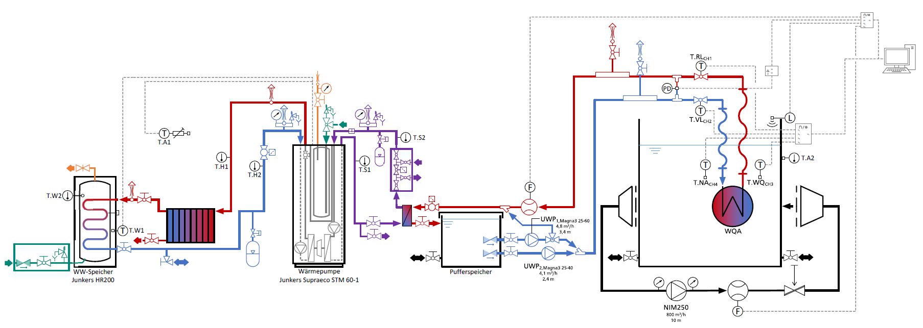
The heating circuit consists mainly of the usual components of a heating system. First, a heat pump tempers the heat transfer medium in a buffer basin to the set temperature. Two heating circulation pumps convey the tempered heat transfer medium to the heat source system under study in the study basin. The cooler heat transfer medium flows through the heat source system, absorbing heat energy from the surrounding, warmer river water. Subsequently, the heated heat transfer medium flows back into the buffer basin. The excess heat energy is transferred to the research laboratory via a hot water tank and radiators.
The inlet and outlet temperatures on the heat transfer medium and flow water side are measured at the heat source system under study and the temperature spreads and gradients are derived from them. In addition, the pressure drop is measured at the heat source system under study.
Key data:
- Flow rate heat transfer medium: Grundfos MAGNA3: 0 to 4.8 m3/h
- Nominal heat output heat pump: Junkers Supraeco STM 120-2: 10 kW
- Flow measurement: electromagnetic flowmeter (MID) Endress+Hauser Promag W400
- Inlet and outlet temperature measurement: JUMO Pt100 resistance temperature sensor in four-wire circuit and tolerance class AA
- Pressure drop measurement: differential pressure sensor Hottinger Baldwin PD1
- Gradeness: up to 8°K (system-dependent!)
- Storage tank volume Buffer tank: ≈ 1.36 m3
- Characteristic curves of extraction rates of different heat source systems for different flow velocities and temperatures
- Biofilm investigations
- Operating limits
- Local temperature changes in the stream due to a heat extraction operation
- Flow effects of heat source plants
- Calibration and validation for numerical flow simulations
- Open systems with river water extraction
- Sensitivity studies for the test procedure