
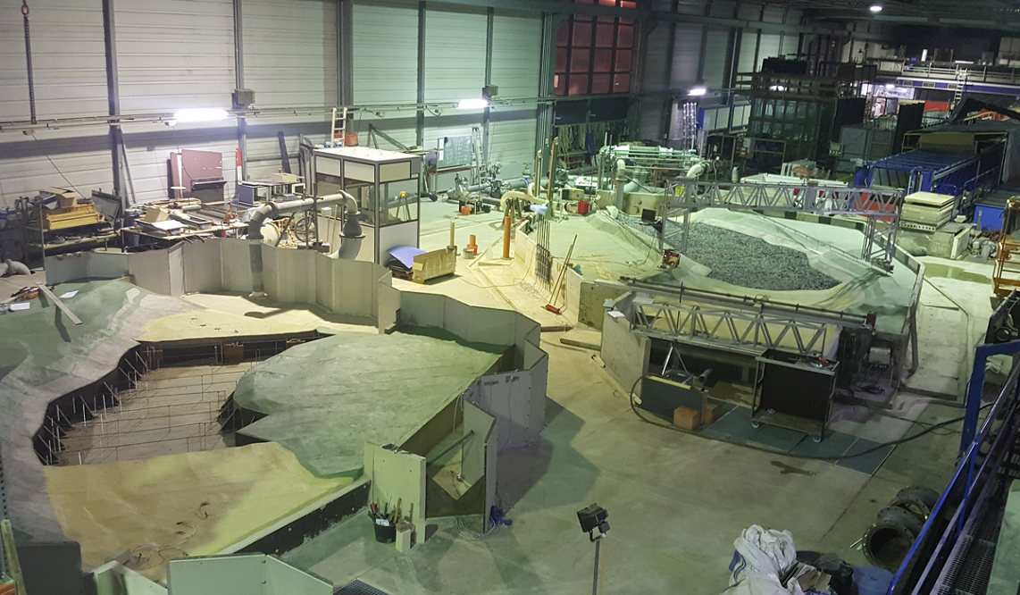
In the rear area of the hydraulic engineering research laboratory, there is an area that is primarily available for physical model experiments (in the following figures, the area is located in the research laboratory). The model scale is chosen for the creation of the models in such a way that the same values for the process-relevant dimensionless ratios occur in the model as in nature. Due to extensive experience and the infrastructure available in the hydraulic engineering research laboratory, the research laboratory offers excellent possibilities to run models according to the similarity criteria or the applicable model laws.
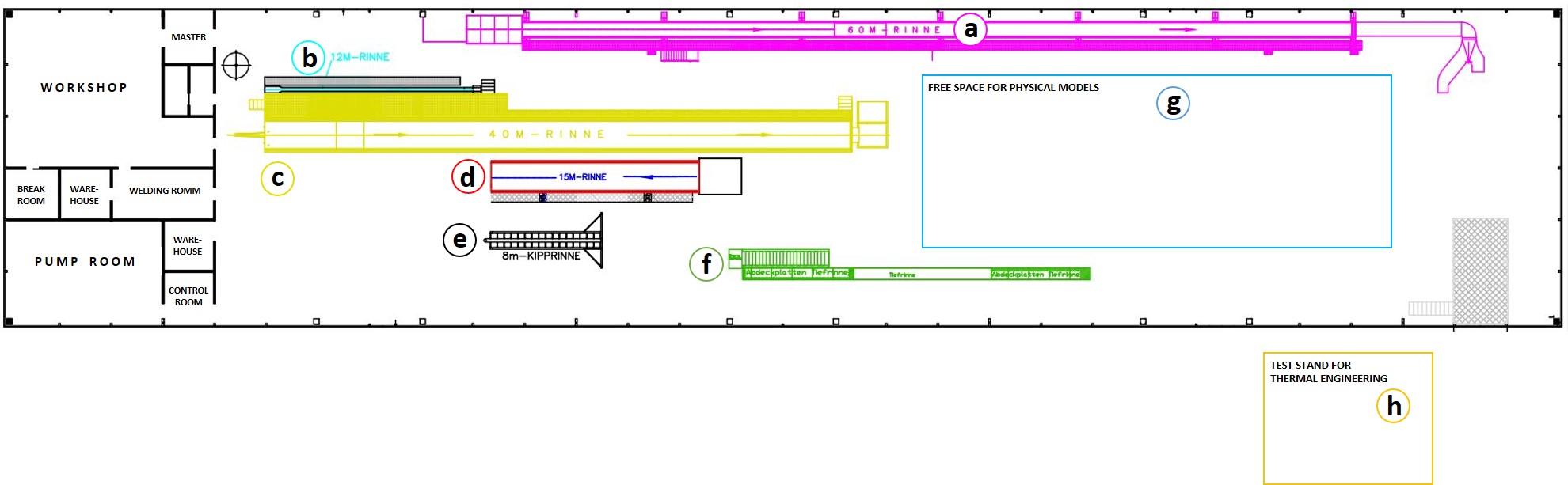

It is ensured here that the model parameters can be designed accordingly so that similarity is ensured with regard to the flow events at the model edges, in the area of the watercourse, at the structures to be considered and in the adjacent areas. When determining the model location within the open space in the research laboratory, it is taken into account as far as possible that decisive areas of the selected model section can be extended or adapted for future supplementary investigations if required.
Usually, the hydraulic engineering model is inserted into a masonry, concrete or steel-wall element border. The geometry of the watercourses to be depicted is prepared from georeferenced profiled sheets. Due to the filling of the gaps and the application of a concrete cover layer in the model, the terrain can be simulated in a geometrically similar way. During the construction, sufficient flexibility and mobility of the components relevant to the investigation is ensured in order to be able to change individual contours, openings or geometries at short notice and without much effort during the work, if necessary.
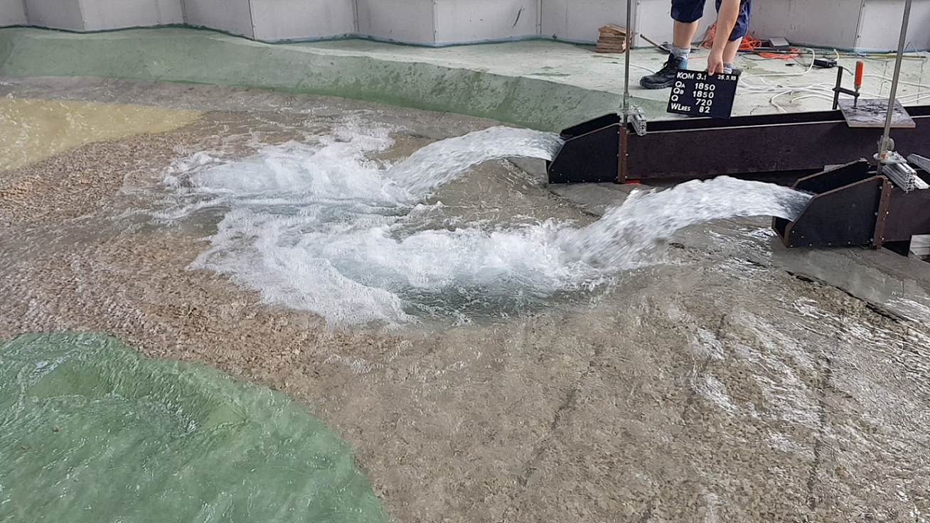
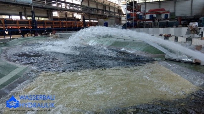
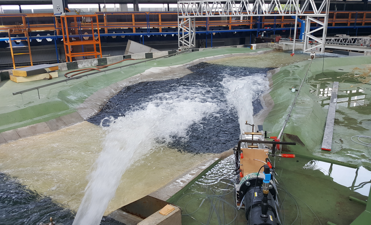
The model is controlled by water level-discharge relationships for the mapped area. By means of inductive flow measurements at the inlet pipes, the injected quantities can be recorded and controlled via arranged gate valves. Motor-driven butterfly valves at the model outlets are used to set the associated water levels in the model. The measuring and control instruments are connected to a control computer, which enables and controls the exact setting of the hydraulic boundary conditions.
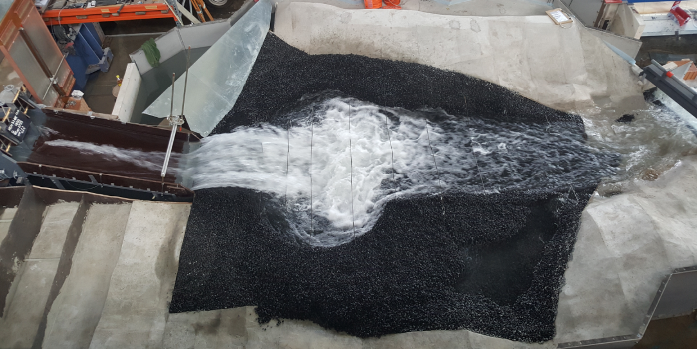
If sediment transport processes or erosion and sedimentation processes are the focus, similarity is to be achieved due to the choice of a suitable bed material. Here, if necessary, artificial grain material is also used in addition to the natural sediments.