60 m – Flume
- Length: 60 m
- Broad: 1 m
- Height: 0,8 m
- Maximum flow: 400 l/s
- Feature: tiltable
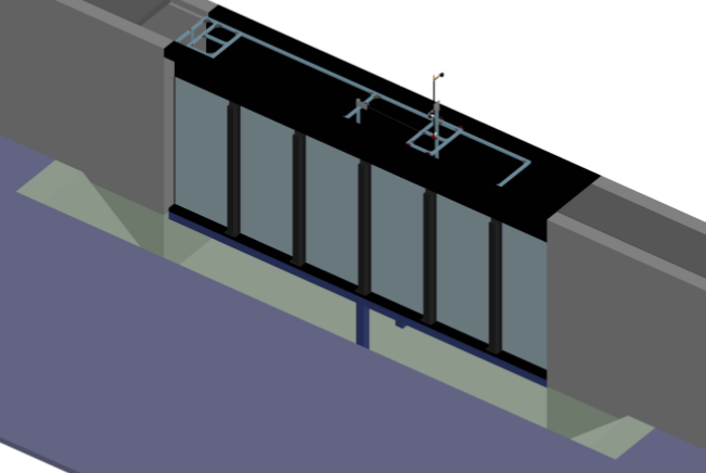
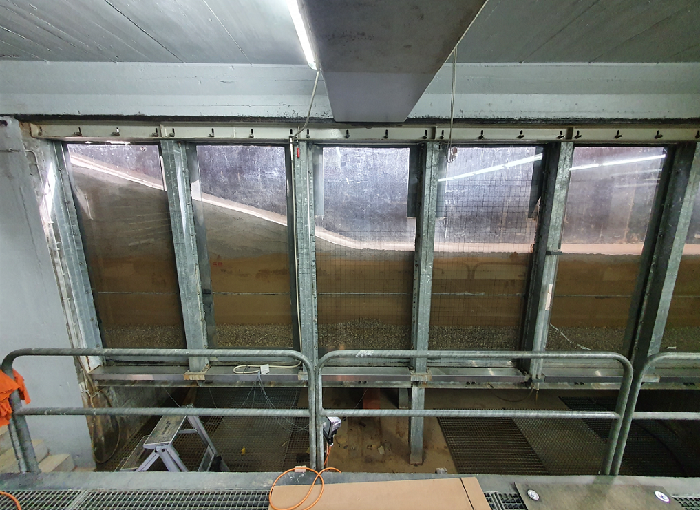
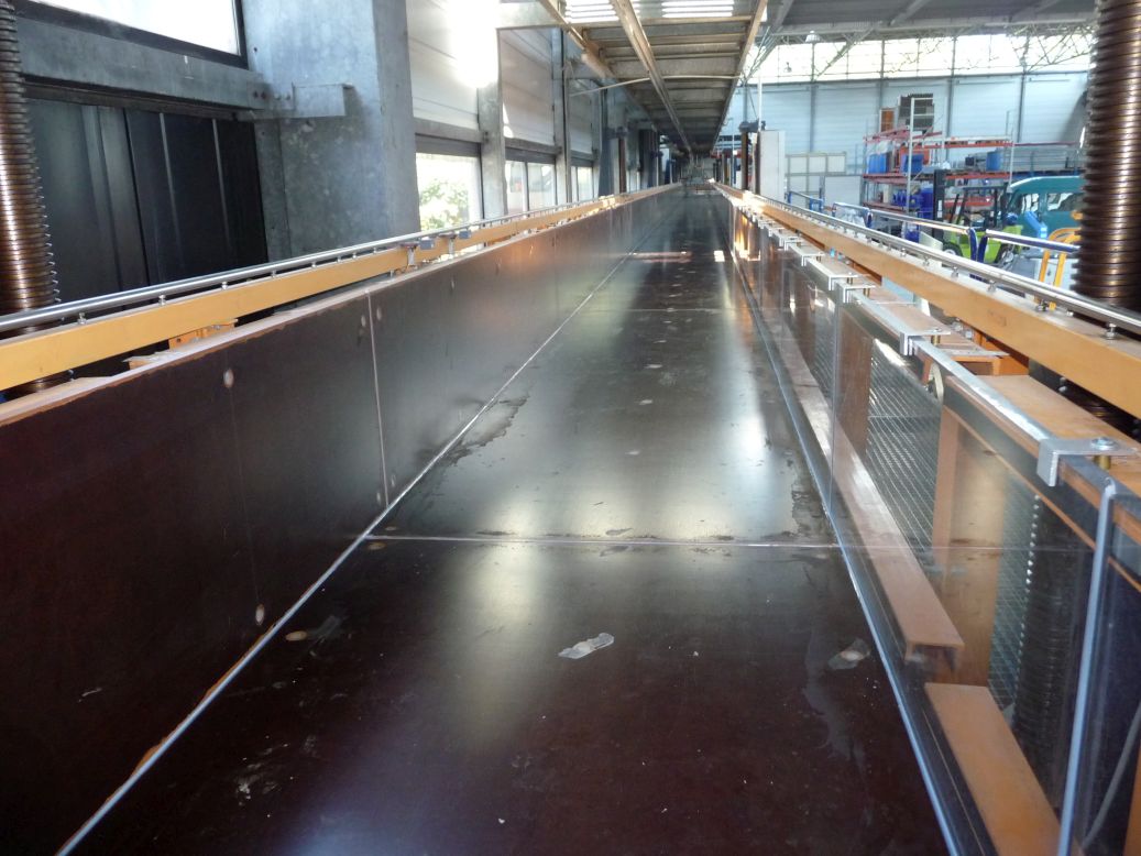
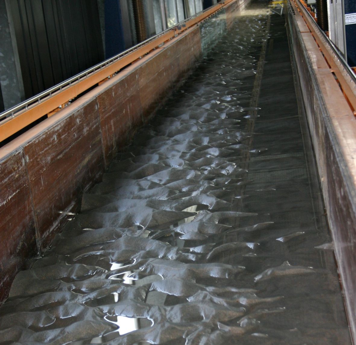
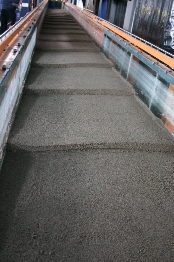
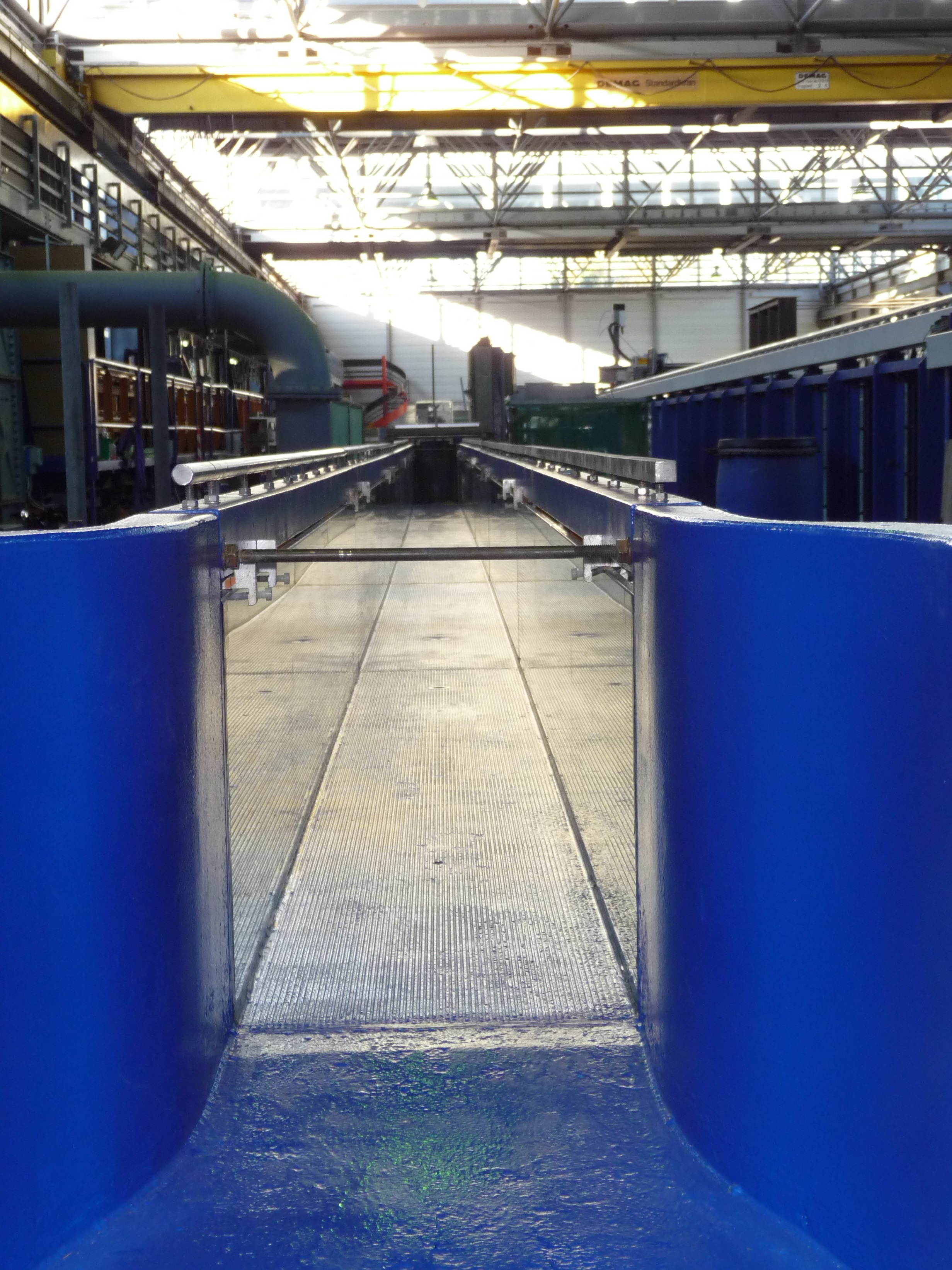
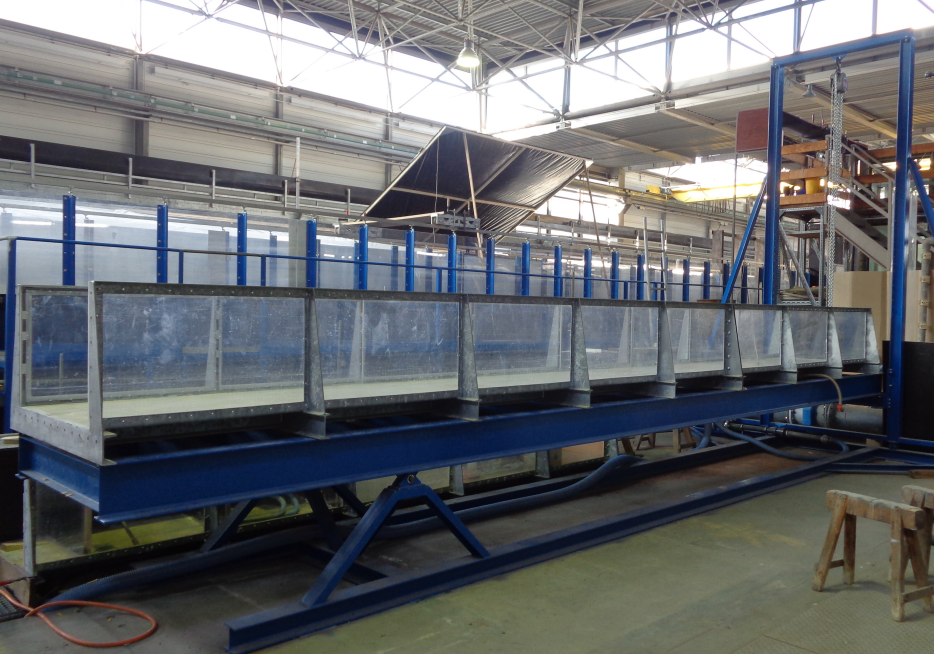
The large tipping trough in the WBFL has a length of 60m. The inner, usable cross-sectional profile is 1m wide and 0.5m high. The right side wall, viewed in the direction of flow, is designed with acrylic glass panels so that the flow conditions can be viewed from one side over the entire length of the trough.
A fundamental prerequisite for work in accordance with the state of the art and science is the use of suitable measuring equipment. These measuring devices must be subject to some kind of monitoring by means of tests and comparative measurements. Thus, in addition to the pure use of measurement, there is always a need for verification or calibration equipment. This necessity is addressed by the 60m flume at the WBFL of the TU Darmstadt, because its purpose is, among other things, the further development of experimental test equipment for velocity and flow measurements: Since the velocity of the approaching water often cannot be simulated with sufficient accuracy and consistency, the various measuring devices are dragged here at different velocities through a channel with standing water (drag channel). Since the distance to be covered in the drag channel is known, only the time required for this has to be measured exactly and the number of revolutions in the case of the vane or the speed in the case of directly indicating measuring systems has to be registered. The prerequisite is that the movement of the measuring carriage with the measuring instruments mounted on it is kept as constant as possible over the entire measuring run.
12 m – Flume (internship flume)
- Length: 12 m
- Broad: 0,3 m
- Height: 0,35 m
- Maximaler Durchfluss: 30 l/s
- Feature: tiltable
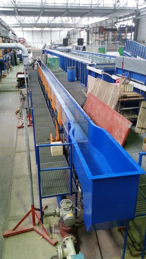
The so-called practical flume of the hydraulic engineering research laboratory of the TU Darmstadt is 0.3 m wide, 0.3 m high and has a measuring range of about 12 m in length. Flow rates in the range of 0 to 30 l/s can be adjusted via a remote-controlled slide valve. Adjustment of the bed line slope is possible via a threaded mechanism. In addition, the remote-controlled cylinder gate at the outlet of the channel – in combination with the mechanism for adjusting the longitudinal slope – allows the adjustment of different water depths. The measurement control technology of the WBFL offers the possibility for a targeted setting of predefined flows and water levels.
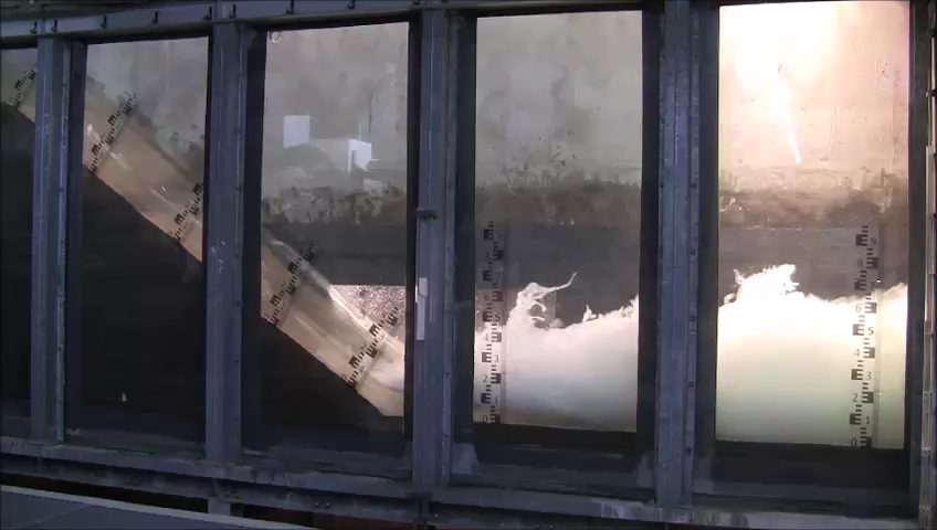
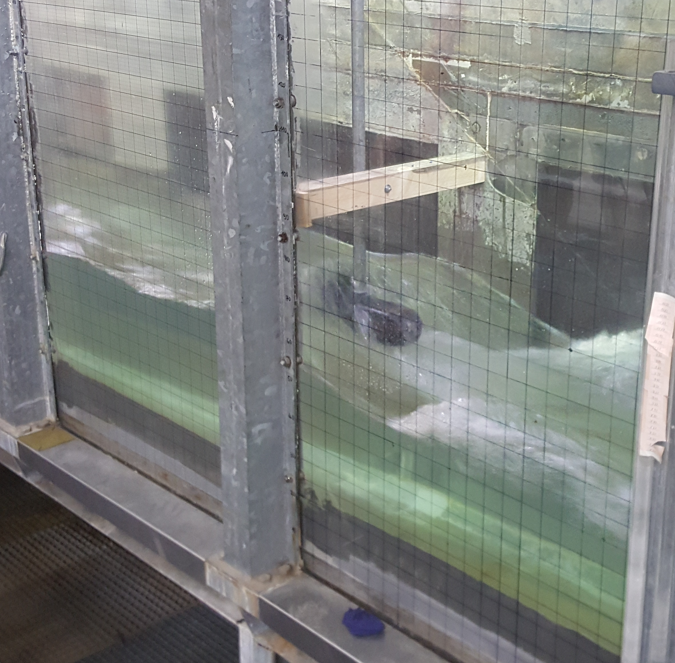
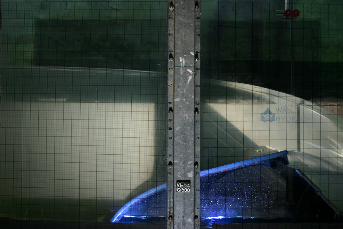
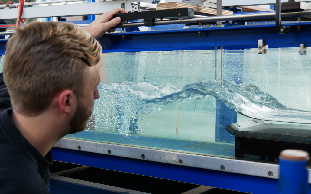
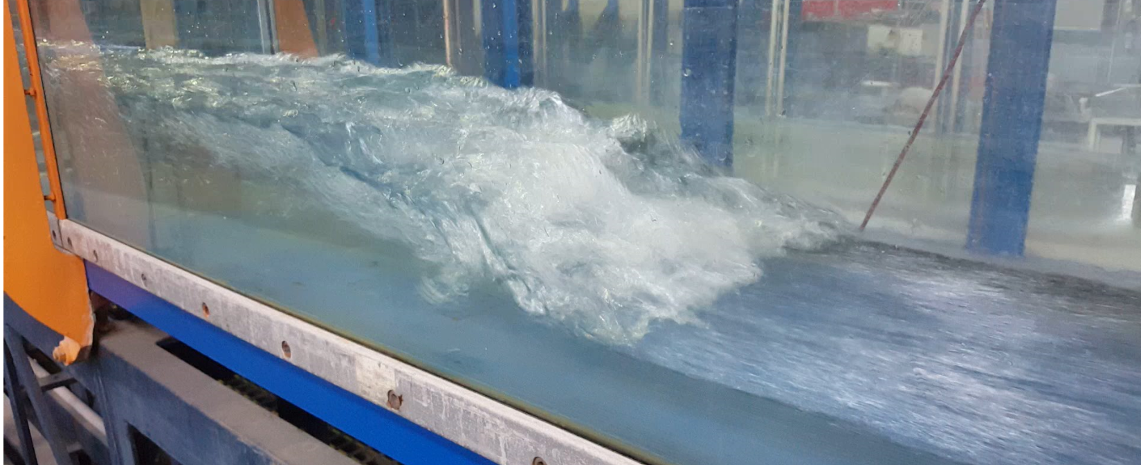
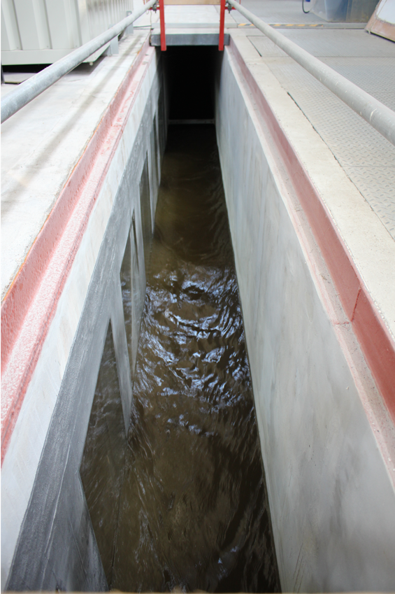
Application example: “Surf wave”
A standing wave is stationary. For suitable surfing conditions, it should, among other things, have as smooth a water surface as possible. Responsible for the generation of such a wave in this case is the special manifestation of a phenomenon that is called alternating jump in channel hydraulics. Up to now, these waves have been generated mainly in structures for energy conversion (stilling basins) or by chance – for example, due to flood events or improperly dimensioned structures. Based on the growing public interest, however, there are now also efforts on the part of science to optimize this type of wave generation for other uses.
Which structural measures can be used to generate such waves in flowing waters? For this purpose, a model on a scale of 1:15 was made and tested in the so-called “practical flume” under various conditions. The so-called “maximum wave” with Froude numbers in the range of 2.0 to 4.0 and an adapted tailwater level proved to be particularly suitable for wave generation. Structurally, a combination of bottom step and ramp was used. In practice, controlled inflow and outflow conditions are required above all, so that such a wave is conceivable in conjunction with a reservoir or an additional headrace channel.

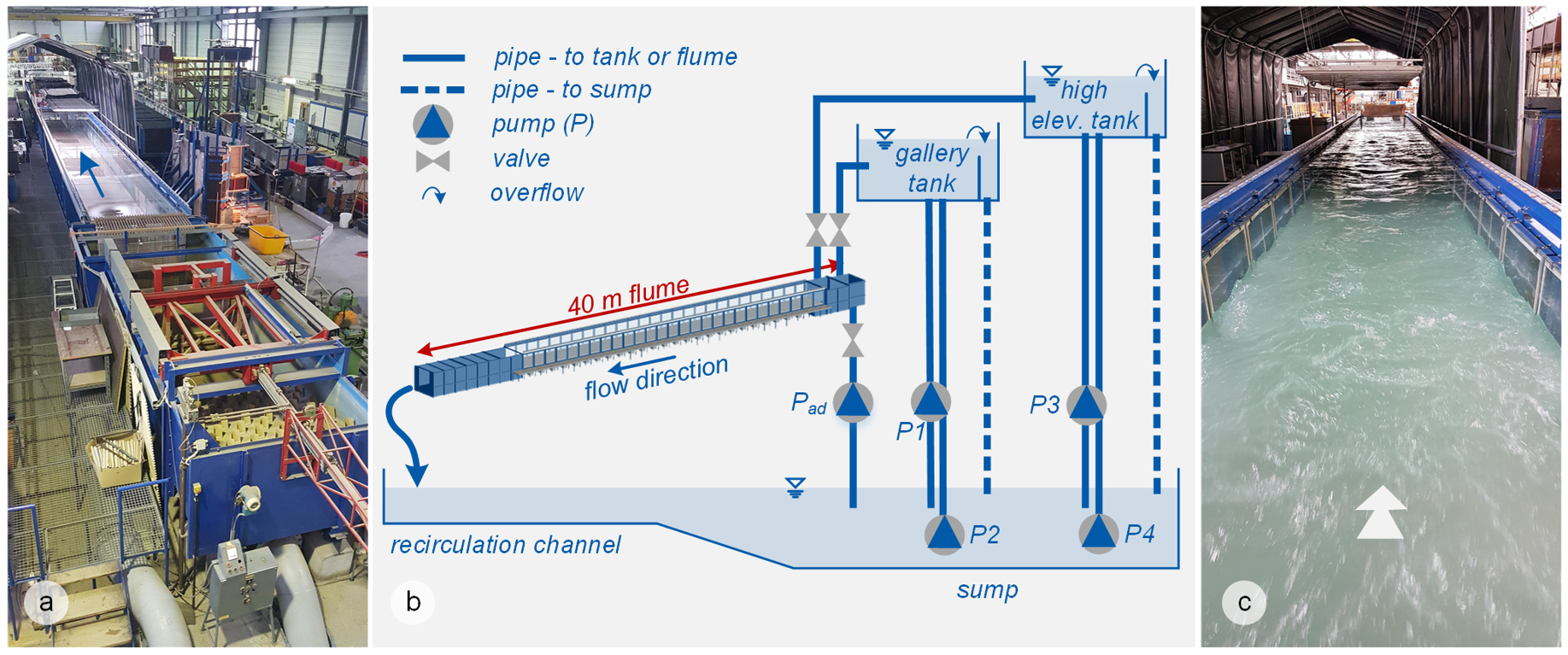
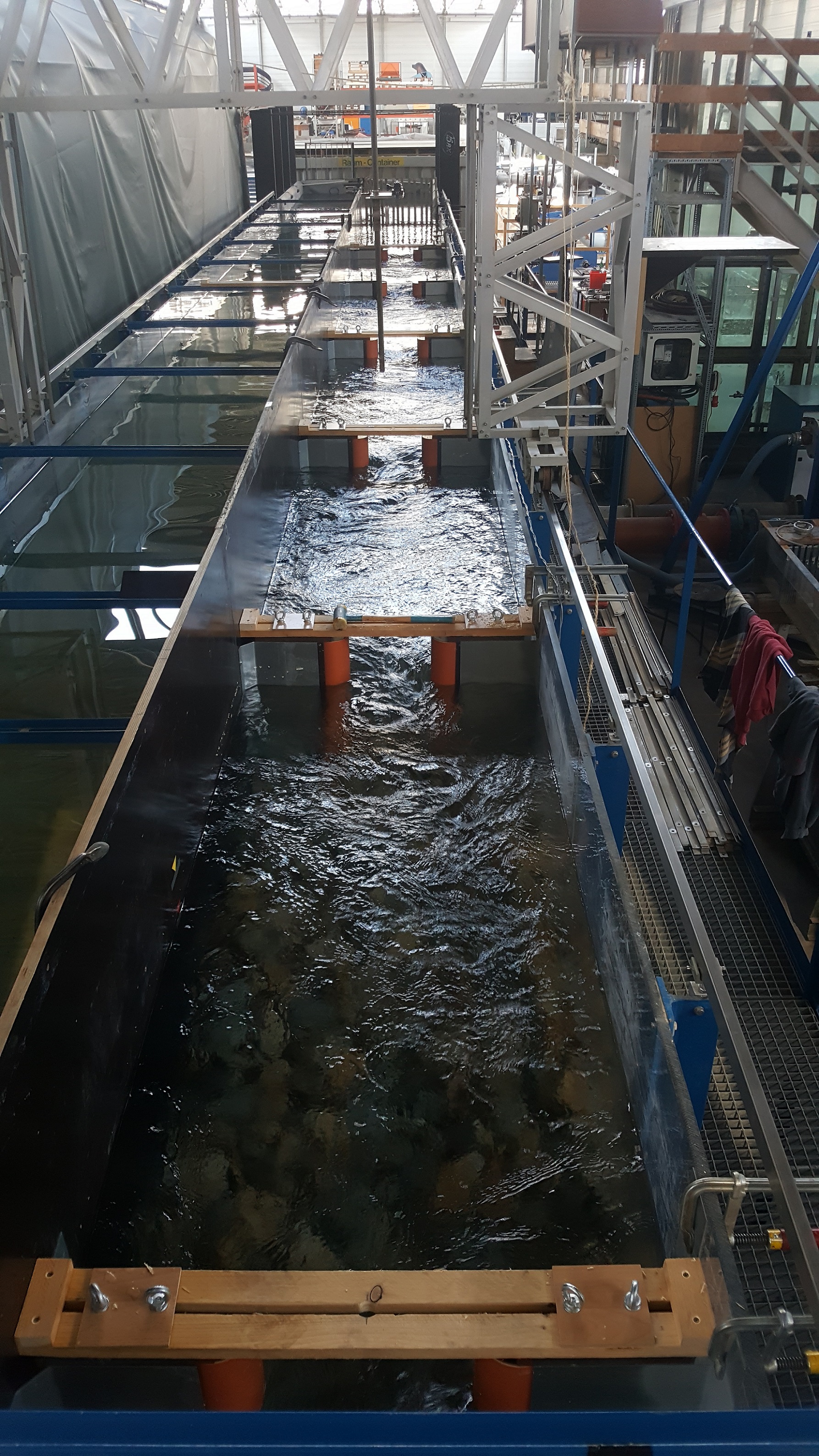
40 m – Flume
- Length: 40 m
- Broad: 2 m
- Height: 1 m
- Maximum flow: 1000 l/s
- Feature: wave machine
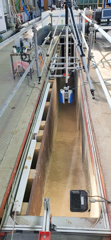
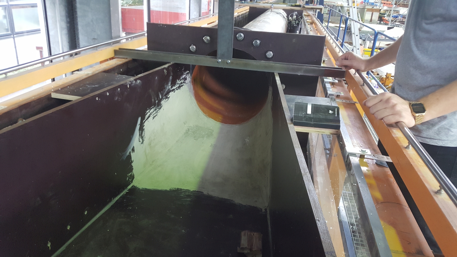
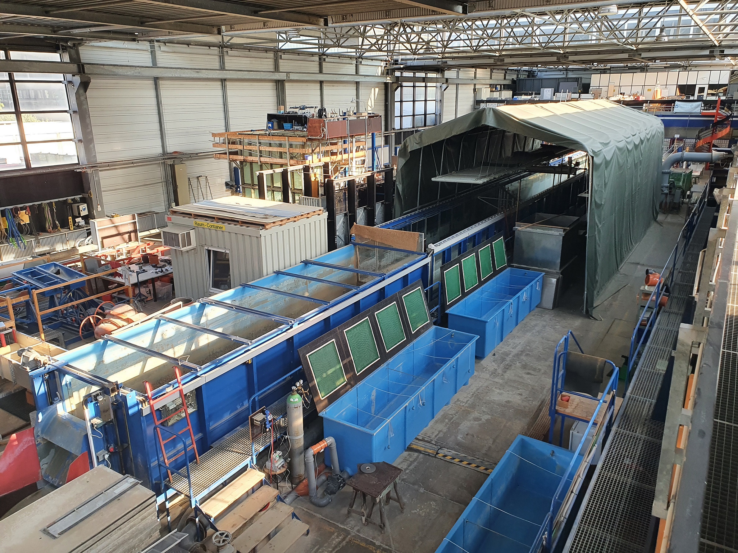
Currently used primarily for ethohydraulic studies, the flume in the research laboratory is 40 m long. The inner, usable cross-sectional profile is 2 m wide and 1 m high. The side walls of the flume are constructed with glass panels so that the study area can be viewed over a length of 27 m. The flume's central section is also visible from the outside. In addition, the central area of the flume is covered with a large tent in which different lighting situations can be simulated. With the help of several pumps, the flume can be flowed through at up to 1 m³/s.
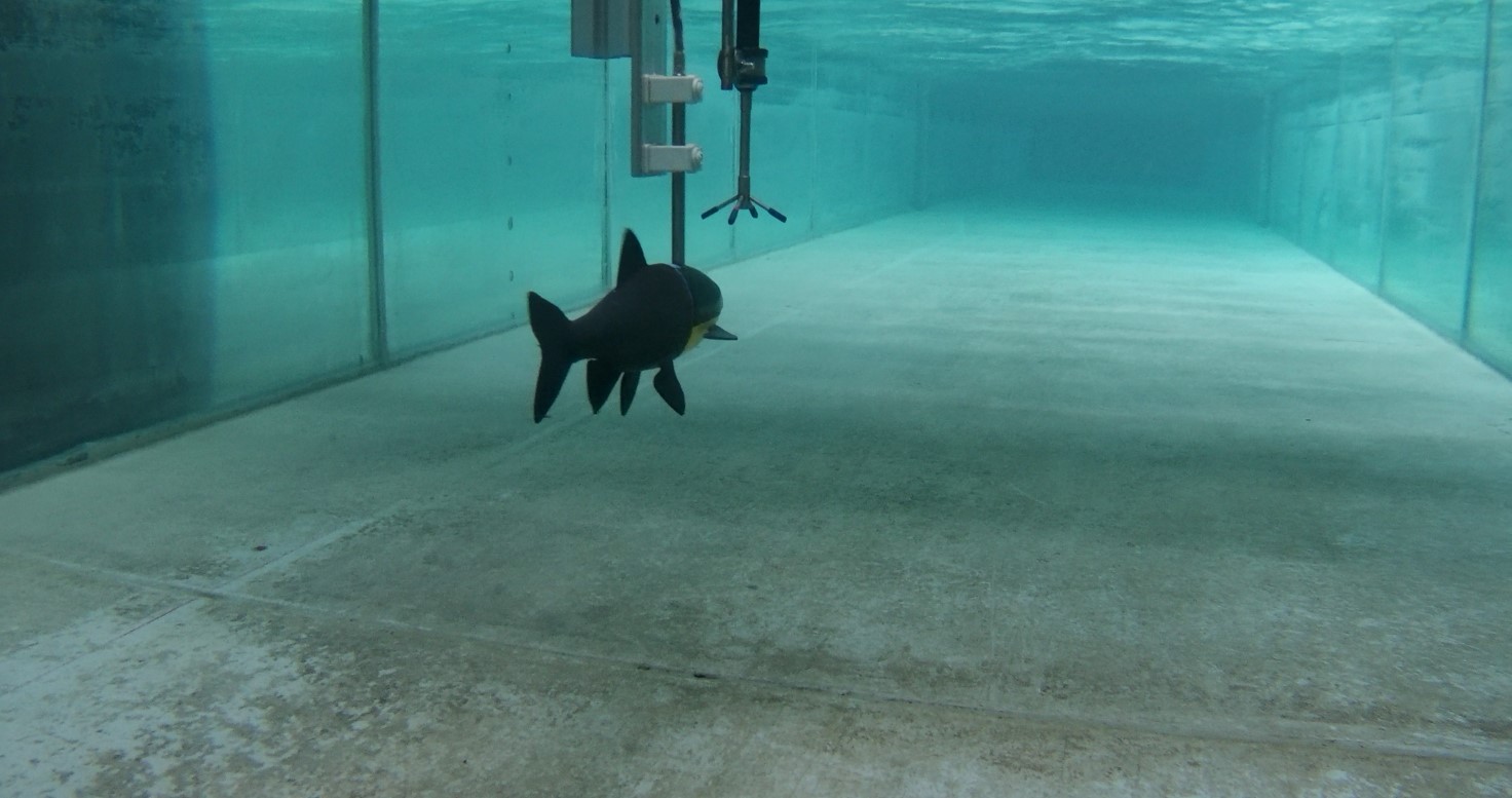
The experimental flume of the hydraulic engineering research laboratory of the TU Darmstadt has already been successfully used in several ethohydraulic research projects. In addition to fish biological observations, flow signatures were measured and hydrodynamic numerical flow simulations were carried out.
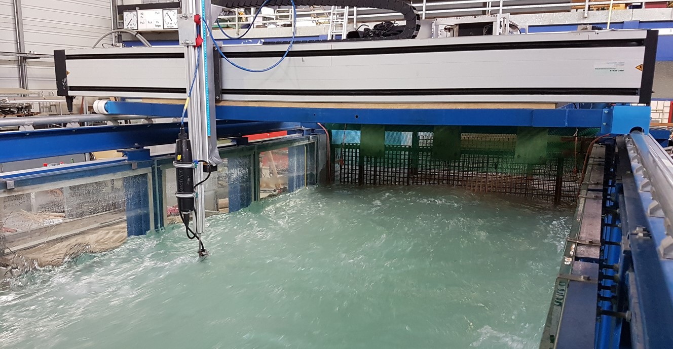
The 40m flume is also used, among other things, to investigate the close-up range of fixtures. For this purpose, a mobile measuring trolley with an automated measuring device positioning system is installed on the flume. Thus, different measurement grids can be specified and these can be traversed with a high degree of accuracy in the individual test series.
A wave generator is also installed in the inlet area of the flume, which enables the generation of waves via a connected hydraulic unit and the controlled movement of a metal shield.
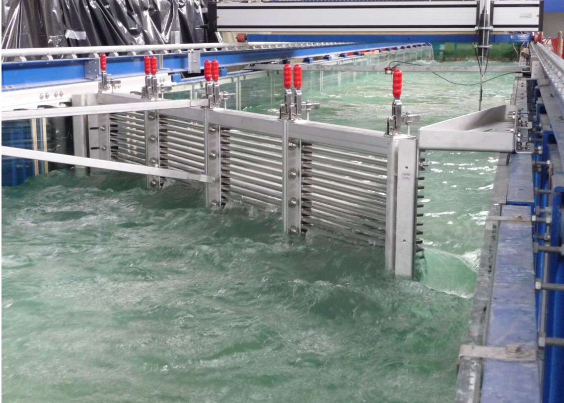
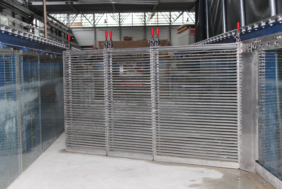
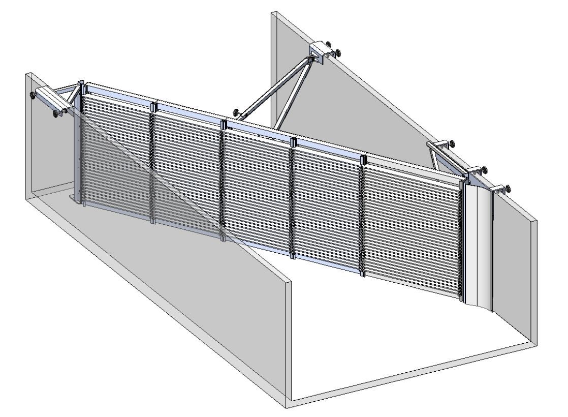
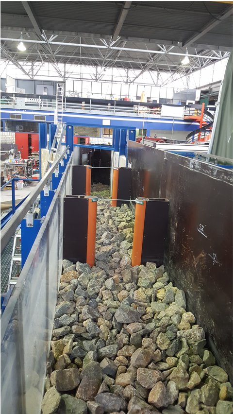
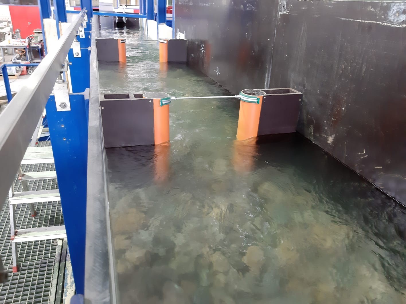
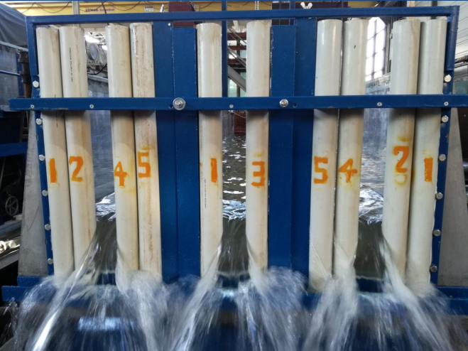
Modular horizontal rake system in the 40 m – gutter
The effect of a horizontal rake on the flow dynamics and fish behavior is often of essential importance and will therefore be investigated in current and future research projects. The main focus is on the question of how a necessary rake system has to be constructed in order to exert minimal influence on the ecosystem and still be efficient for the plant operator. The modular horizontal rake system available at research laboratory was designed to fit two existing experimental gutters and consists of several individual modules, which are connected to each other depending on the angle of attack of the rake.
15 m – Flume
- Length: 15 m
- Broad: 2 m
- Height: 1 m
- Maximum flow: 450 l/s
- Feature: tiltable
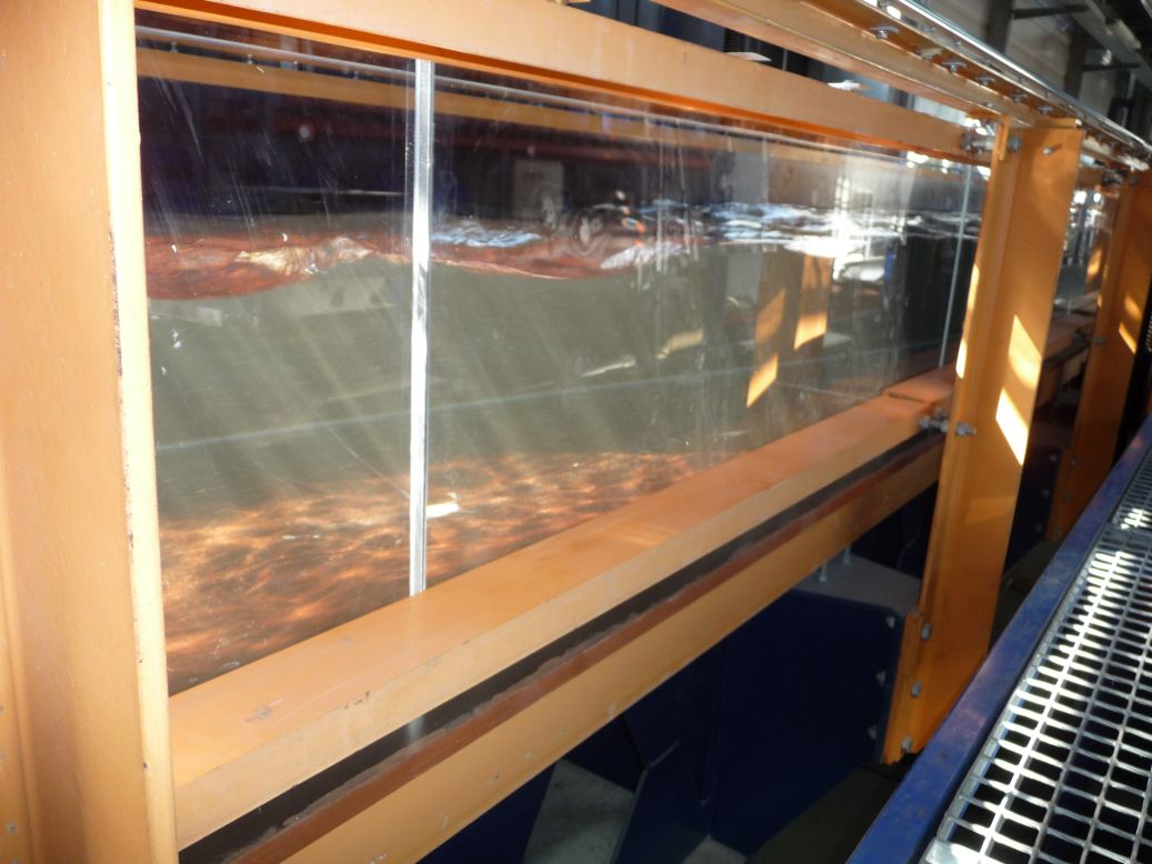
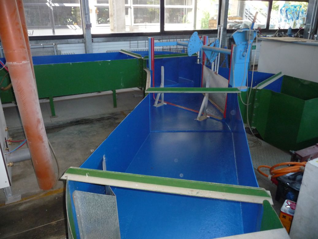
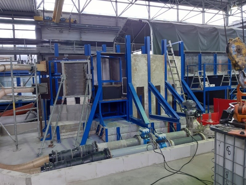
The 15 m flume has an internal, usable cross-sectional profile with a breadth of 2 m and height of 0.8 m. The side walls of the trough are made of acrylic glass, so that the examination area can be seen. In addition, the trough can be divided longitudinally by a partition wall, which enables advantageous conditions depending on the scope and purpose of the examination.
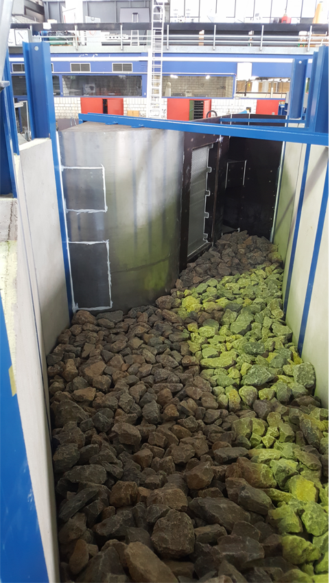
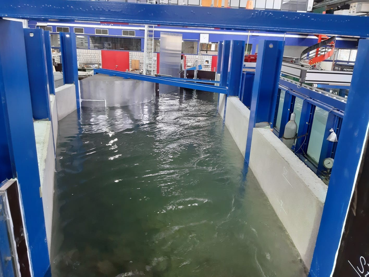
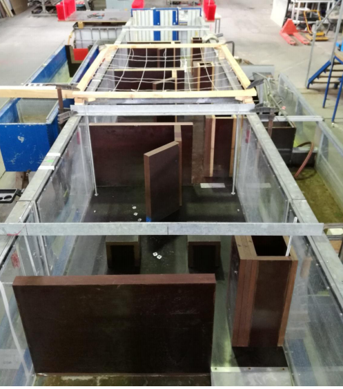
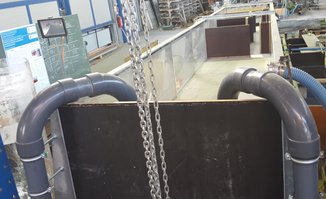
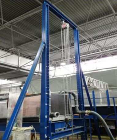
For model investigations, the elevated position of the flume bottom lends itself to the installation of supplementary model setups in the outlet area of the flume and the use of the flume for the simulation or investigation of the inflow situations. This possibility of modeling or experimental model investigation has been used several times in the past. For example, a deepened antechamber with various discharge openings was operated and investigated in various combinations. Pictures of this can be found in the following picture gallery.
8 m -Flume
The 8 m – flume has an inner, usable cross-sectional profile with a breadth of 1 m and a height of 0,6 m. The side walls of the flume are made of acrylic glass so that the examination area can be viewed. In addition, the trough can be tilted longitudinally in a range from -3 to 47 %. The tilting trough is also suitable as a basis for insertable partial models or modules. These can be used according to the plug-in modular principle, for example for different types of fishways.
30 m – Flume (deep flume)
- Length: 30 m
- Broad: 0,75 m
- Height: 3 m
- Maximum flow: 1000 l/s
- Feature: Deep flume
The deep flume, connected to a separate water circuit, has a length of 30 m. The inner, usable cross-section profile is 0.75 m broad and 3 m high. The side walls of the flume are designed with acrylic glass panes in the middle section of the flume, so that the investigation area can be viewed over a length of approx. 7 m. The side walls of the flume are designed with acrylic glass panes. In addition, there is the possibility of installing a movable measuring frame along the flume for recording the measured values. With the help of the installed pump, the flume can be flowed through with up to 1 m³/s.
This experimental flume in the hydraulic engineering research laboratory has already been used successfully in numerous research projects. Due to the relatively large depth compared to the width, the flume has a prominent unique selling point. Among other things, numerous tests have already been carried out here on the characteristics of spillways, inclined rakes and dike cross-sections. In addition, due to its capacity with flows of up to 1 m³/s, the deep flume offers suitable conditions for the investigation of hydrokinetic energy converters.