Chair of Hydraulic Engineering

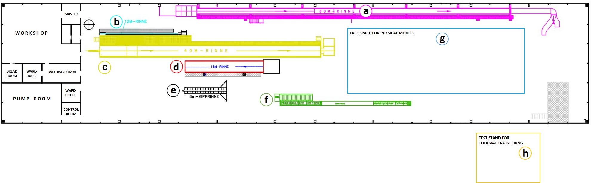
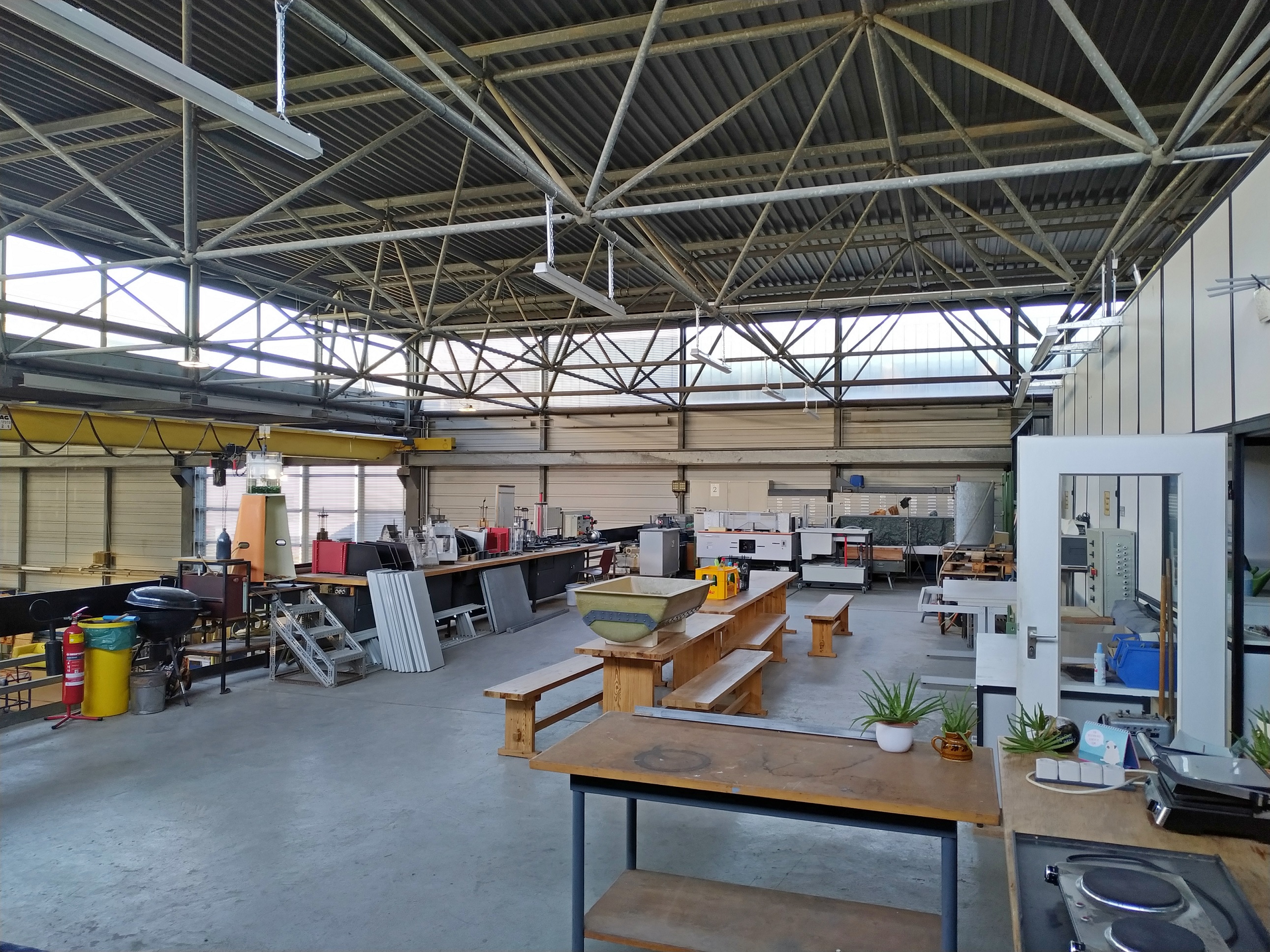
Research Laboratory - Gallery
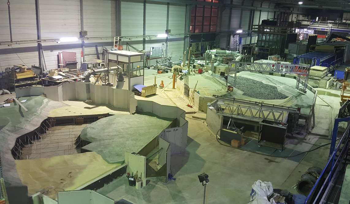
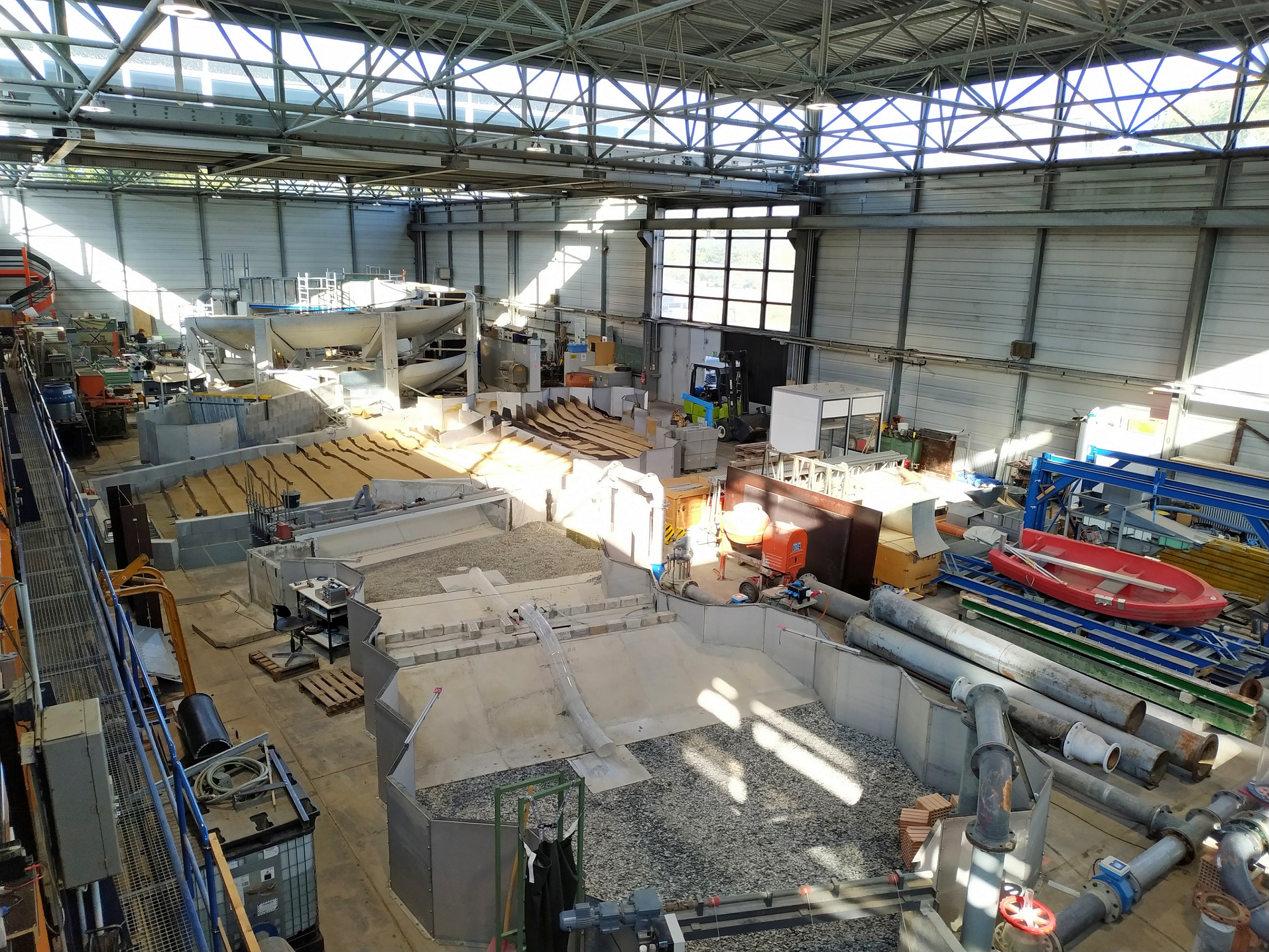
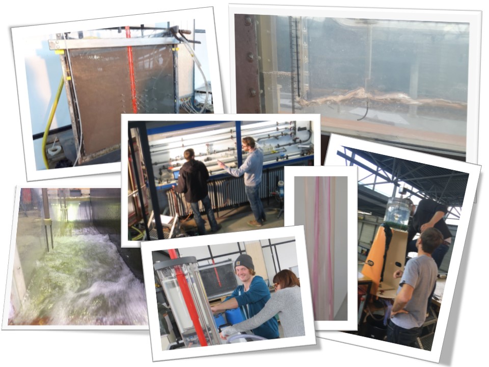
The gallery on the hydraulic engineering research laboratory is intended to provide insights into the measuring equipment available and the investigations carried out on it.


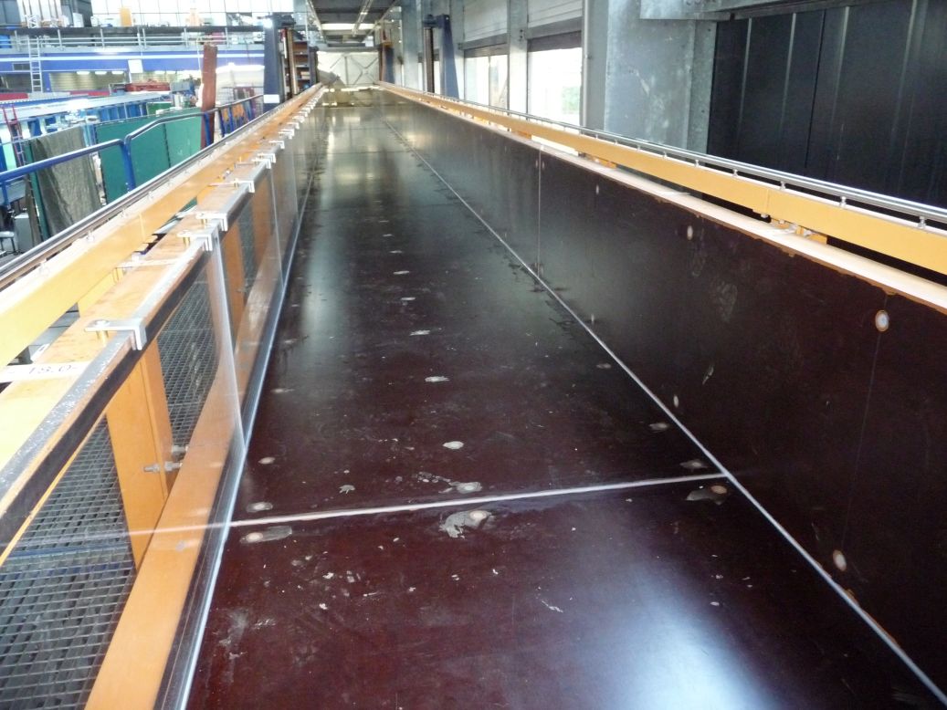
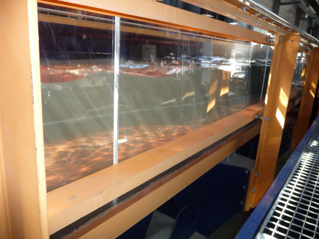
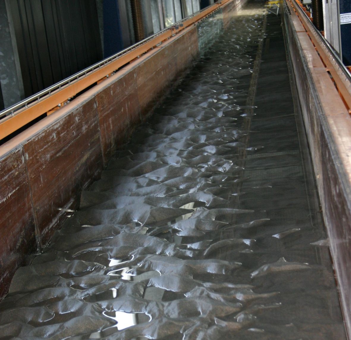
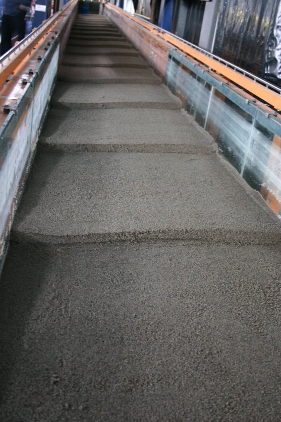
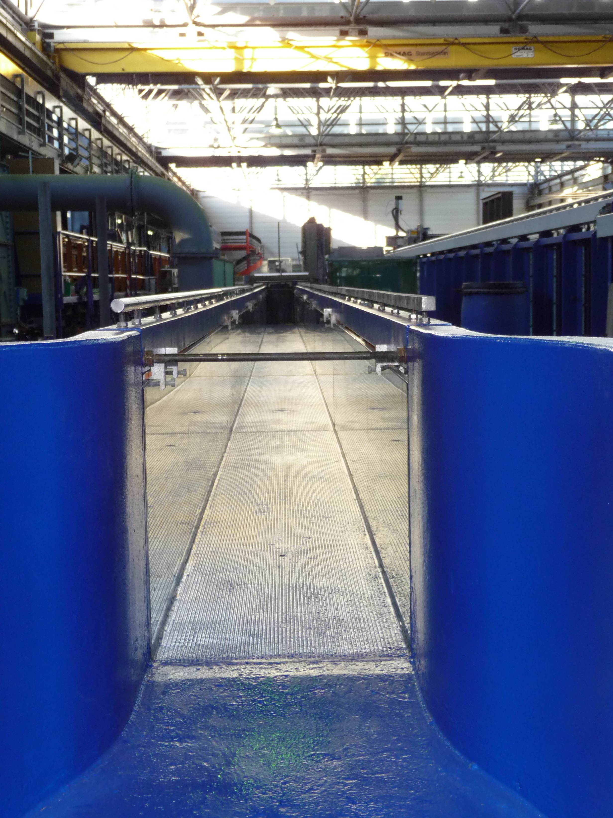
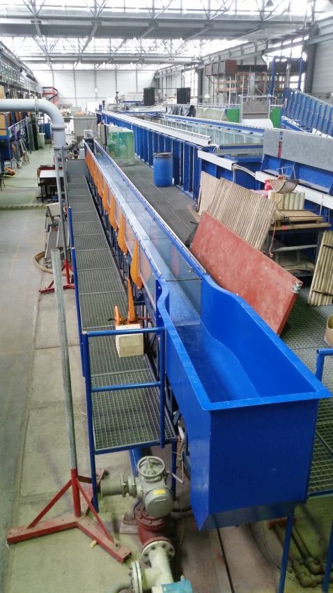

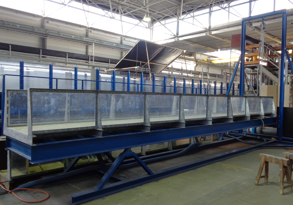
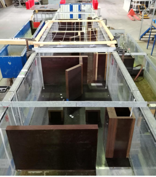
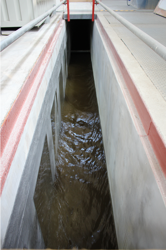
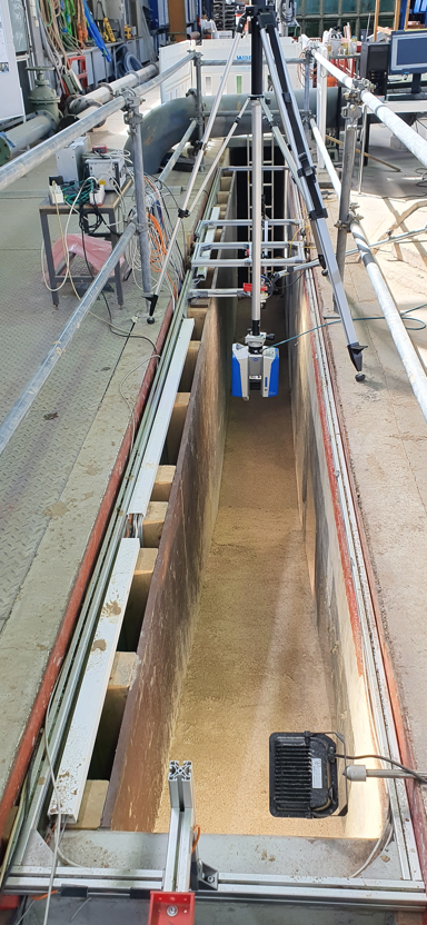
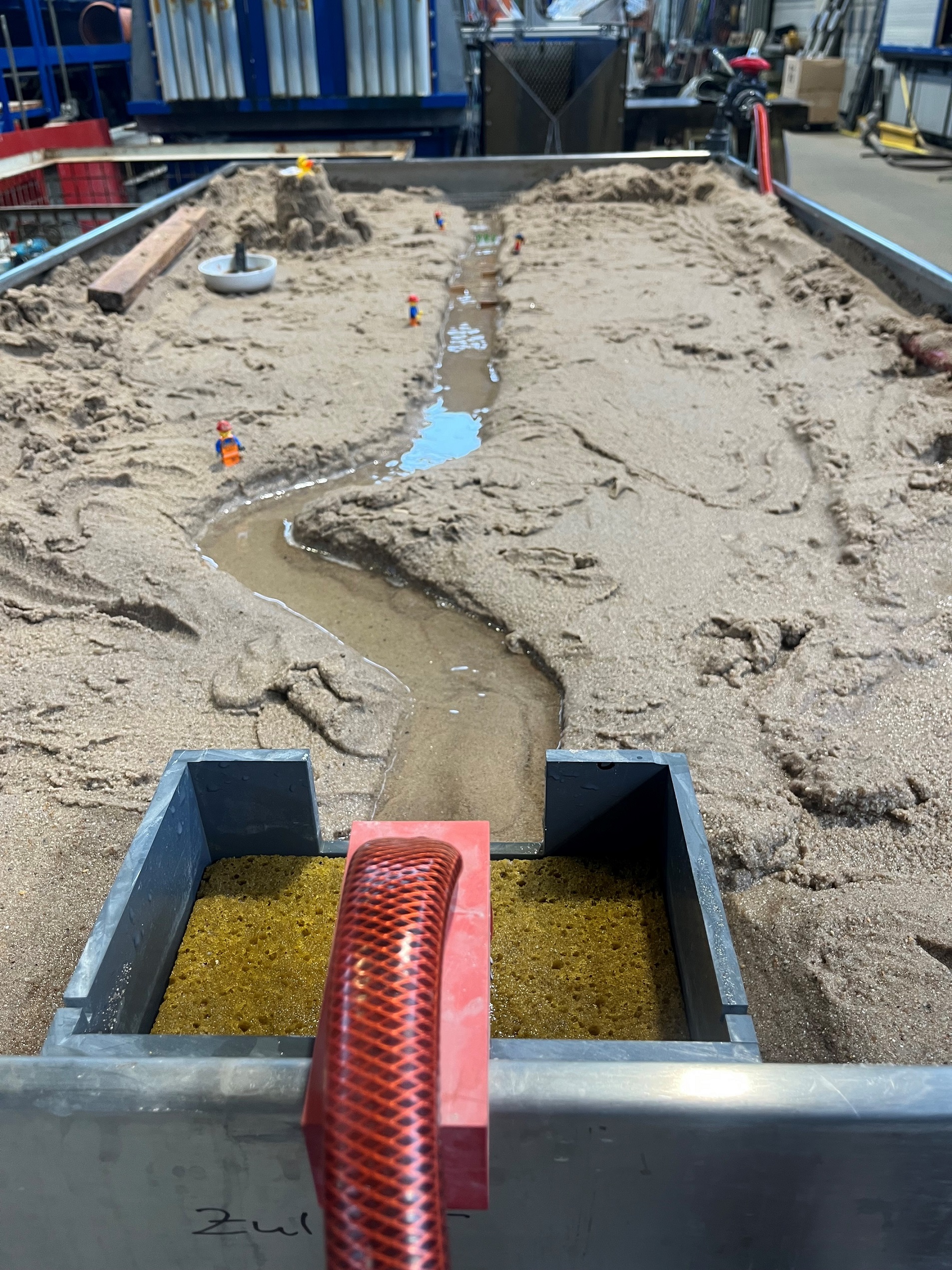
f) Deep Gutter (30 m – gutter)
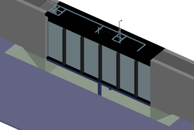
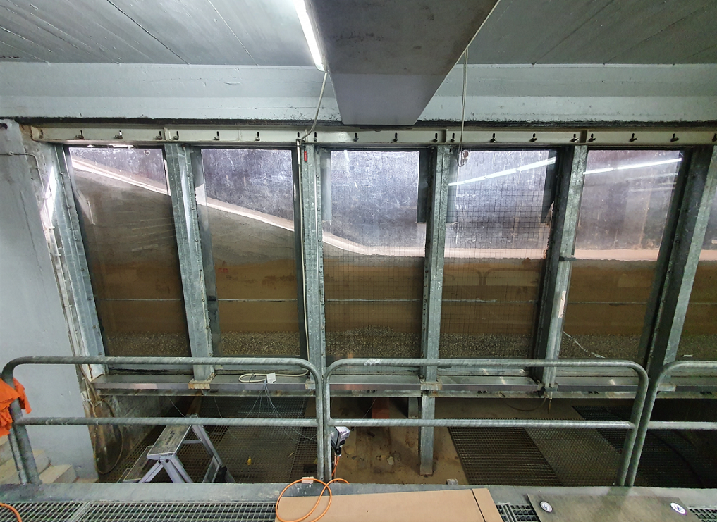
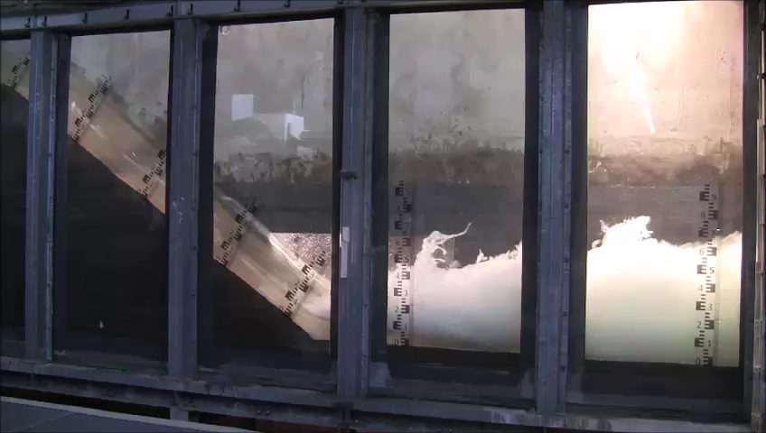
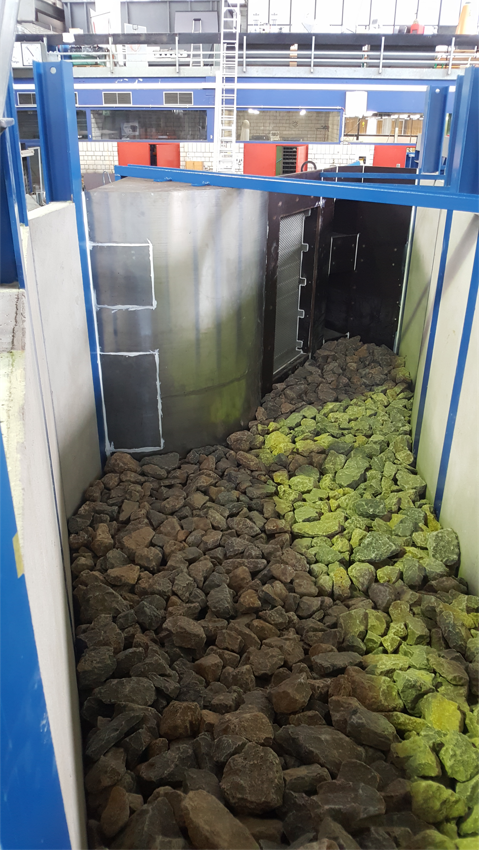
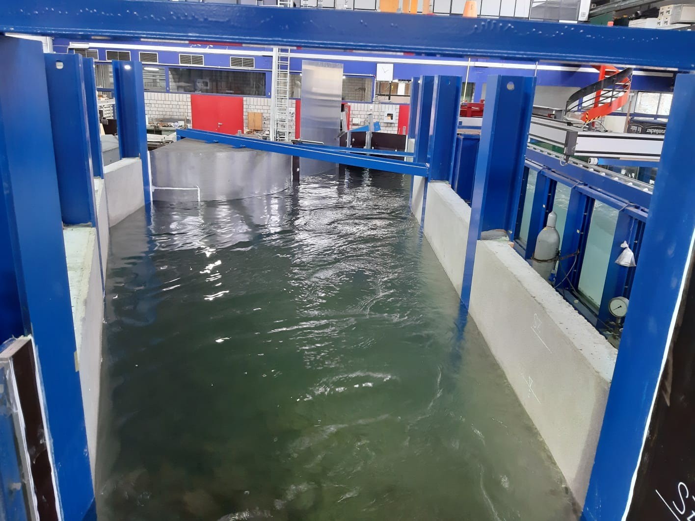
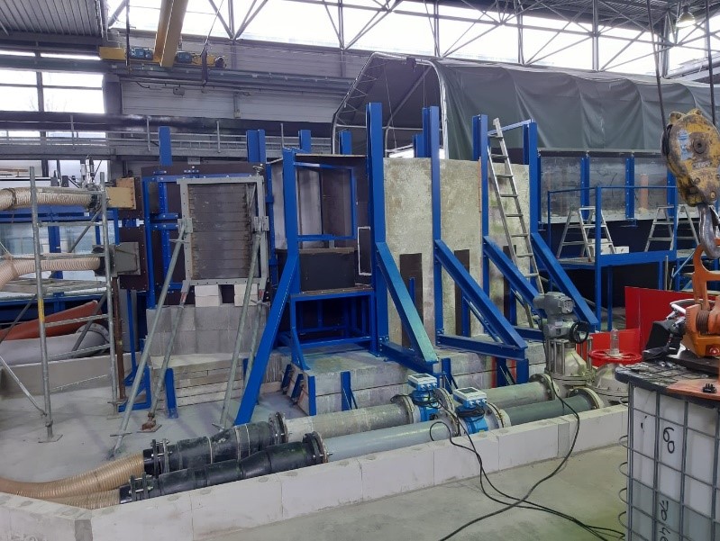
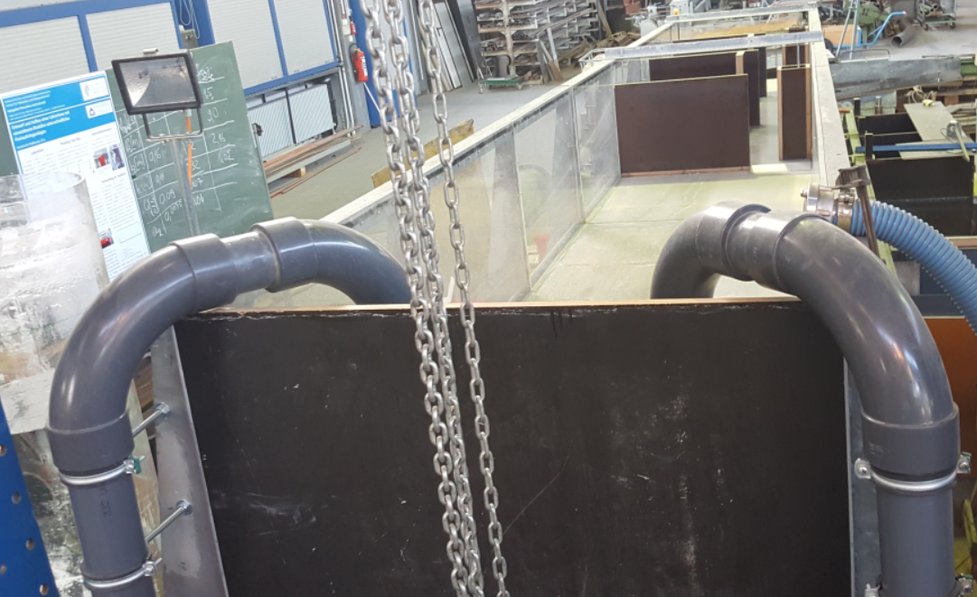
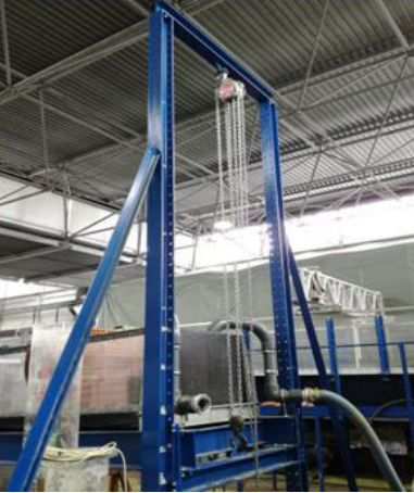
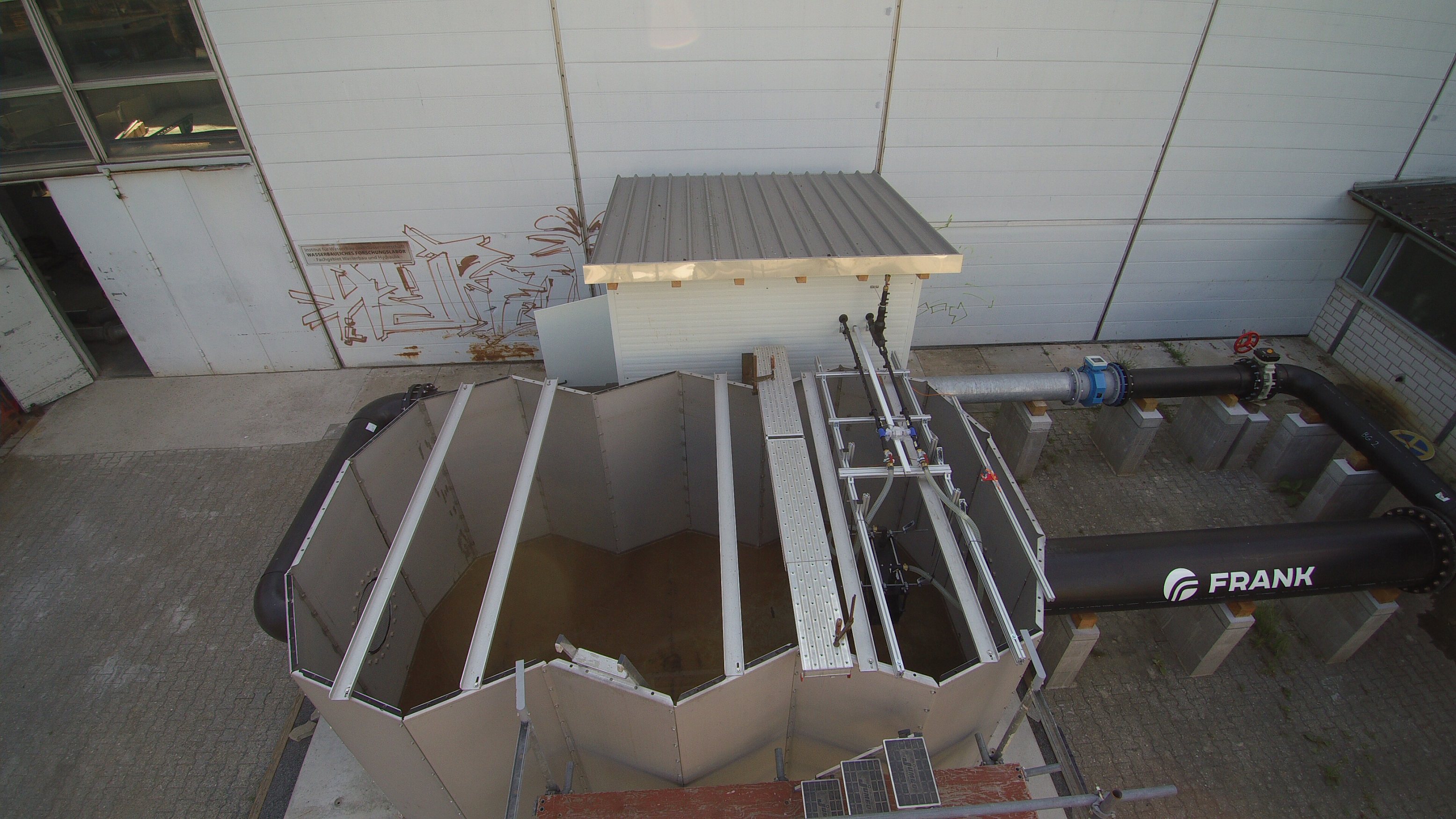
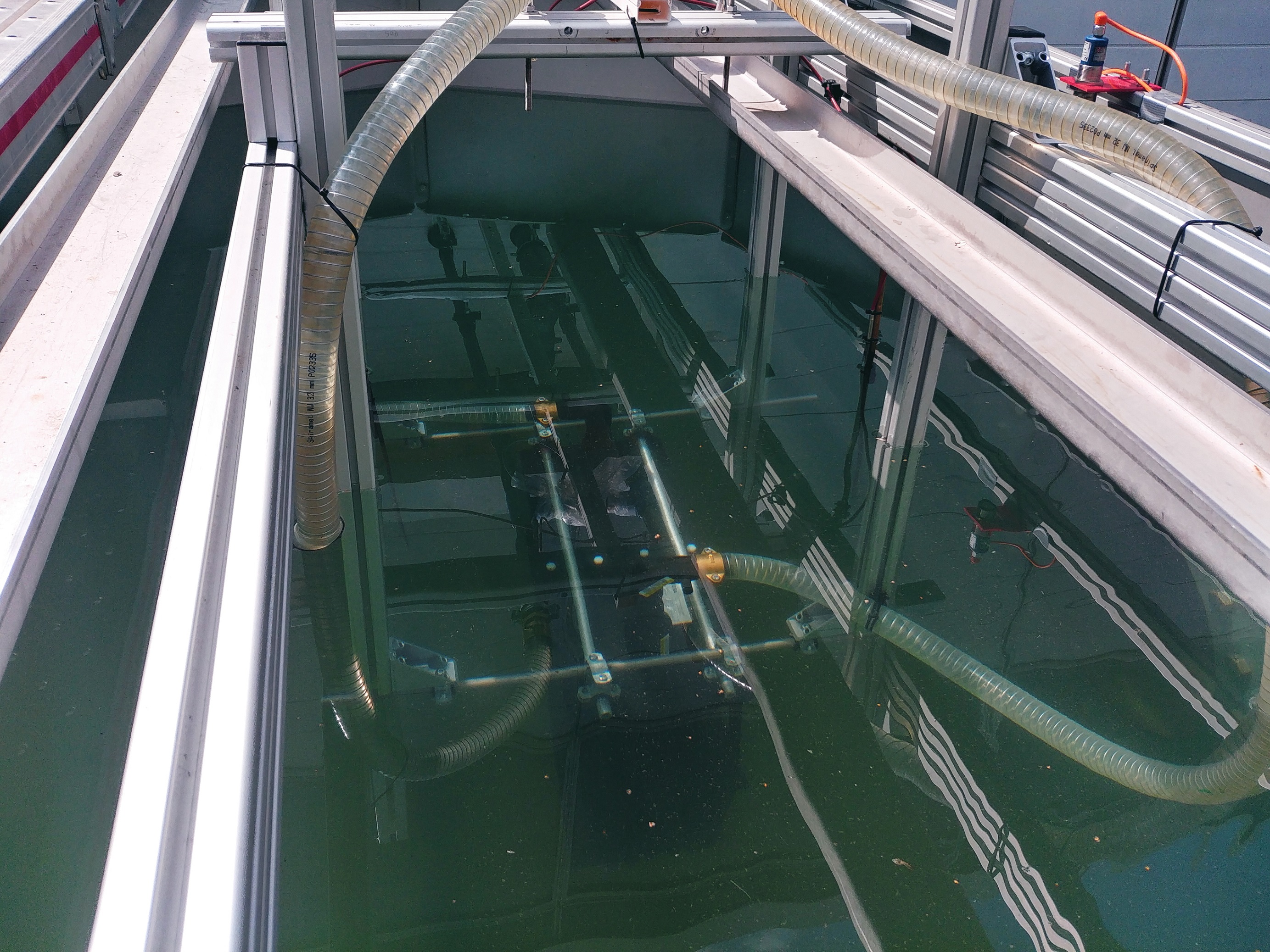
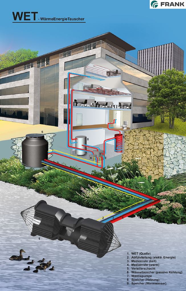
h) Thermotechnical test stand
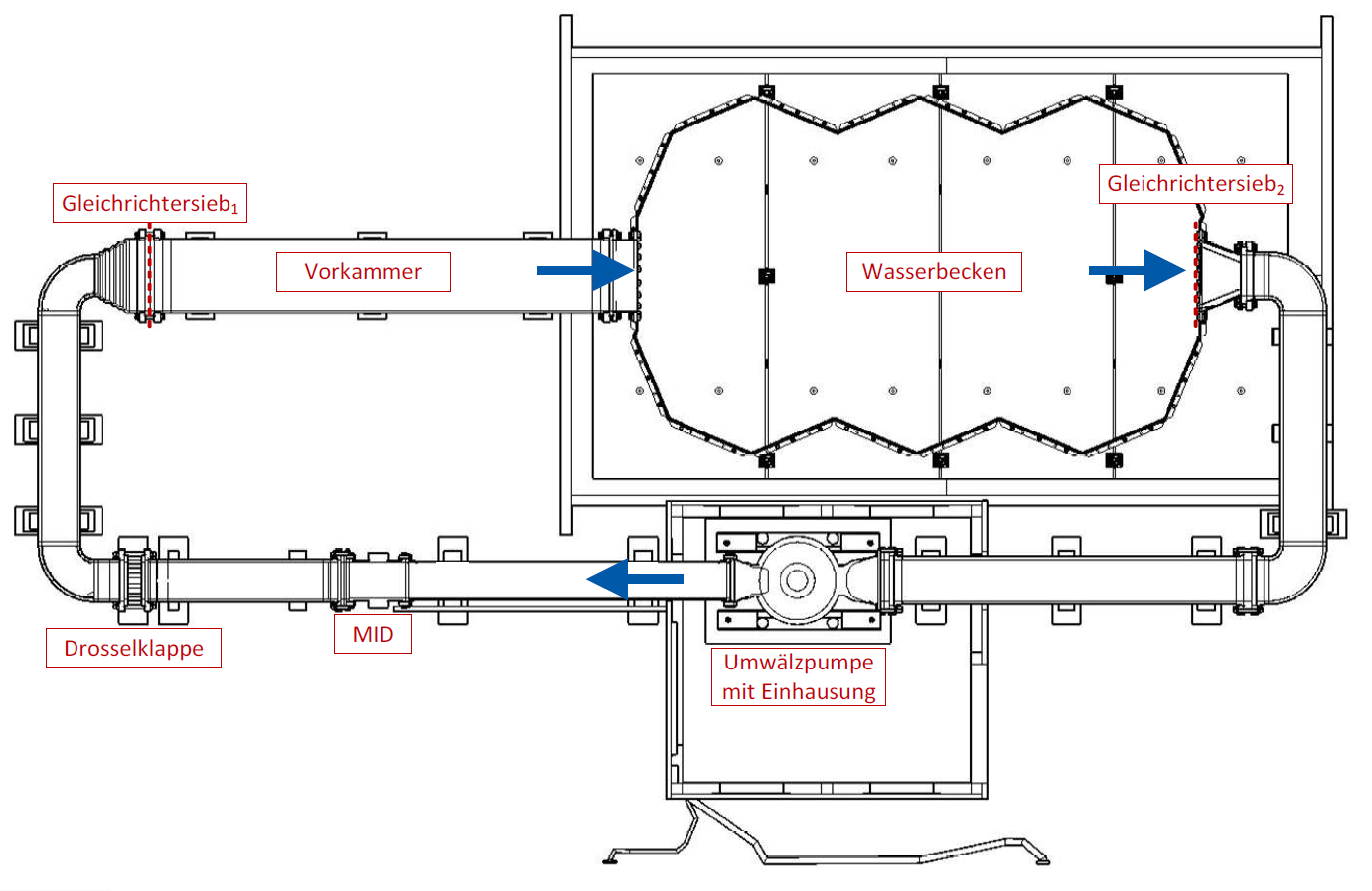
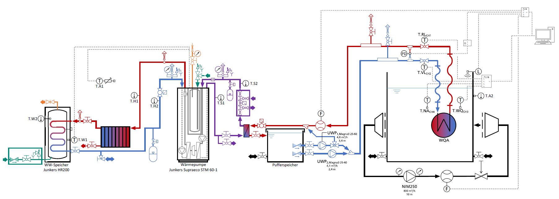
![Geschwindigkeitsverteilung in [m/s] des Tauchstrahls am Ein- (links) und Auslaufrand (rechts) des Prüfbeckens (Simon 2019)](/media/fachgebiet_wasserbau/forschungslabor_voruebergehend/waermetechnischer_versuchsstand/Geschwindigkeitsverteilung.png)
Contact
Sekretariat
wabau@wb.tu-...
work +49 6151 16-21165
Work
L5|01 310
Franziska-Braun-Straße 7
64287
Darmstadt